
If you’re looking for a simple but powerful way to control AC or DC devices over Wi‑Fi, the ESP8266 relay board is one of the best places to start. I’ve used ESP8266‑based boards in many hobby and semi‑professional projects, and relay boards are usually the first real‑world application people build.
In this tutorial, I’ll walk you through exactly how I use an ESP8266 relay board, from understanding the hardware to writing the firmware and controlling a relay over Wi‑Fi. This is written as if I’m personally guiding you through the process.
What Is an ESP8266 Relay Board?
An ESP8266 relay board combines two things on one PCB:
- ESP8266 Wi‑Fi microcontroller (usually ESP‑12 / ESP‑12F)
- One or more mechanical relays for switching higher‑voltage or higher‑current loads
Because the ESP8266 has built‑in Wi‑Fi, the relay can be controlled:
- From a web browser
- From a phone app
- From another server or IoT platform
This makes it perfect for:
- Home automation
- Smart switches
- Remote power control
- IoT experiments
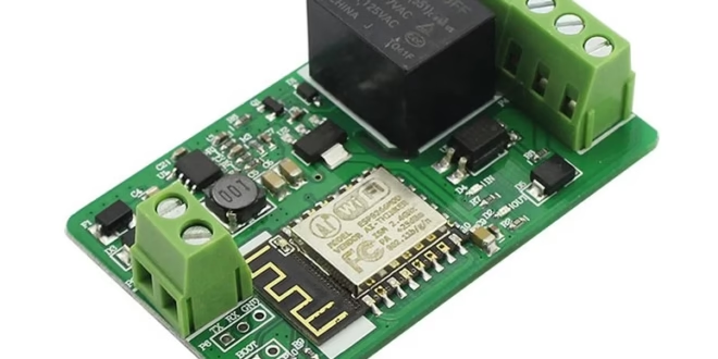
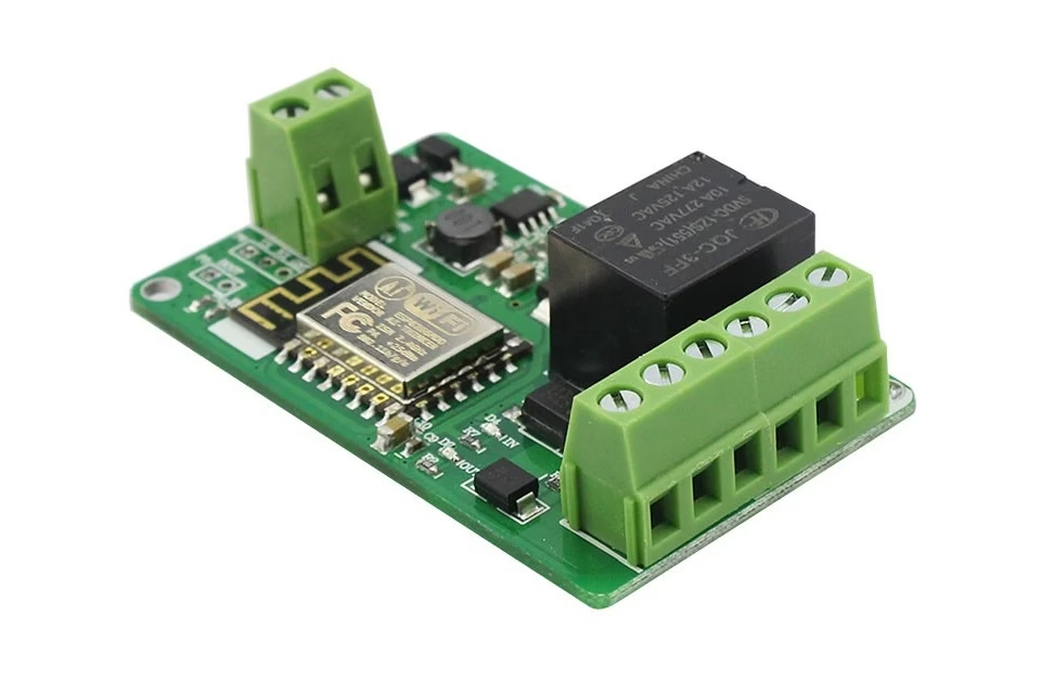
Typical ESP8266 1-Channel Relay Board Features
This guide is specifically written for a 1-channel ESP8266 relay board, which is the most common and beginner-friendly version.
- A: 7-30V+ DC power supply
- B: Power supply ground
- C: ESP8266 Serial Port (Used to program the ESP8266)
- D: ESP8266 Boot Select
- E: Normally closed (NC) relay contact
- F: Common (COM) relay contact
- G: Normally open (NO) relay contact
- H: 5V+ out
- I: ESP8266 GPIO5 Optocoupler Input
- J: Ground (isolated optocoupler input)
⚠️ Important: Even though the ESP8266 runs at 3.3V, the relay side may switch 110V / 220V AC.
Understanding the Relay Terminals (Very Important)
Each relay has three main terminals:
- COM (Common) – the moving contact
- NO (Normally Open) – disconnected when relay is OFF
- NC (Normally Closed) – connected when relay is OFF
How I usually wire it
- For devices that should be OFF by default → I use COM + NO
- For devices that should be ON by default → I use COM + NC
Powering the ESP8266 Relay Board
This is where many beginners make mistakes.
Common power options
- 5V via Micro‑USB (recommended if available)
- 5V to VIN pin
- External regulated 5V supply
The onboard regulator converts 5V → 3.3V for the ESP8266.
⚠️ I avoid powering relays from weak USB ports. Relays draw surge current when switching.
ESP8266 GPIO Pin Used for a 1-Channel Relay
On a 1-channel relay board, only one GPIO is used to control the relay.
Before coding, I always:
- Check the board schematic or silkscreen
- Test the relay manually with a simple sketch
My board uses GPIO4 to control the relay. This is shown in the schematic:
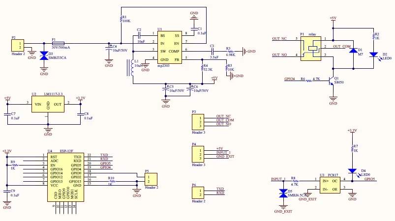
⚠️ Some GPIOs affect boot mode (GPIO0, GPIO2, GPIO15). Using the wrong pin can prevent booting.
Programming the ESP8266 Relay Board
What I use
- Arduino IDE
- ESP8266 Board Package
- USB‑to‑Serial driver (CH340 or CP2102)
Adding ESP8266 to Arduino IDE
- Open Arduino IDE
- Go to Preferences
- Add this URL to Additional Boards Manager URLs: https://arduino.esp8266.com/stable/package_esp8266com_index.json
- Install ESP8266 Boards from Boards Manager
Simple Relay Control Code (My Go‑To Test Sketch)
This is the first sketch I upload to confirm the hardware works.
#define RELAY_PIN 4  // change based on your board

void setup() {
  pinMode(RELAY_PIN, OUTPUT);
  digitalWrite(RELAY_PIN, LOW); // relay OFF (some boards are inverted)
}

void loop() {
  digitalWrite(RELAY_PIN, HIGH); // relay ON
  delay(2000);
  digitalWrite(RELAY_PIN, LOW);  // relay OFF
  delay(2000);
}
If the relay clicks every 2 seconds, your board is working.
Relay Logic: Normal vs Inverted
Many ESP8266 relay boards are active‑LOW, meaning:
- LOW → Relay ON
- HIGH → Relay OFF
If your relay behaves backward, simply invert the logic in software.
Controlling the Relay via Wi‑Fi (Web Server Example)
This is where the ESP8266 really shines.
What I usually do
- Run a small HTTP server
- Add /on and /off endpoints
- Control the relay from any browser
#include <ESP8266WiFi.h>
#include <ESP8266WebServer.h>

const char* ssid     = "YOUR_WIFI";
const char* password = "YOUR_PASSWORD";

ESP8266WebServer server(80);

// Pin definitions
#define RELAY_PIN 4   // Relay control (active LOW)
#define OPTO_PIN  5   // Optocoupler input (INPUT_PULLUP)

// State tracking
volatile bool relayState = false;
volatile bool optoState  = false;

// -------------------- Relay handlers --------------------

void handleOn() {
  relayState = true;
  digitalWrite(RELAY_PIN, LOW);   // active LOW
  server.send(200, "text/plain", "Relay ON");
}

void handleOff() {
  relayState = false;
  digitalWrite(RELAY_PIN, HIGH);
  server.send(200, "text/plain", "Relay OFF");
}

// -------------------- Optocoupler handler --------------------

bool readOptoDebounced() {
  // Read optocoupler (normally HIGH, pulled LOW when active)
  if (digitalRead(OPTO_PIN) == LOW) {
    delay(20); // debounce
    if (digitalRead(OPTO_PIN) == LOW) {
      return true;   // opto active
    }
  }
  return false;      // opto inactive
}

void handleInput() {
  optoState = readOptoDebounced();

  if (optoState) {
    server.send(200, "text/plain", "Opto INPUT: ON");
  } else {
    server.send(200, "text/plain", "Opto INPUT: OFF");
  }
}

// -------------------- Setup --------------------

void setup() {
  pinMode(RELAY_PIN, OUTPUT);
  pinMode(OPTO_PIN, INPUT_PULLUP);

  // Relay OFF at boot (safe default)
  digitalWrite(RELAY_PIN, HIGH);

  WiFi.begin(ssid, password);
  while (WiFi.status() != WL_CONNECTED) {
    delay(500);
  }

  // HTTP endpoints
  server.on("/on", handleOn);
  server.on("/off", handleOff);
  server.on("/input", handleInput);

  server.begin();
}

// -------------------- Main loop --------------------

void loop() {
  server.handleClient();
}
Now I can control the relay by opening:
- http://ESP_IP/on
- http://ESP_IP/off
Additional Notes:
- You must connect a separate and appropriate power supply independent of the USB‑to‑Serial programmer when programming. The USB‑to‑Serial programmer probably has insufficient power.
- P5 connector (labeled D in the guide image above) is meant to be jumped together only during programming. When programming is complete, remove the jumper and reboot.
- Connect your USB‑to‑Serial RX to P6 (labeled C) TX, and USB‑to‑Serial TX to P6 RX, and USB‑to‑Serial ground to the ground.
Common Problems
Relay clicks randomly
- Power supply is weak
- Add bulk capacitor (470µF–1000µF)
ESP8266 keeps rebooting
- Relay coil noise
- Poor grounding
- Use opto‑isolated relay board
Board won’t boot
- Wrong GPIO used
- GPIO0 or GPIO2 held LOW at boot
Safety Notes
When switching AC mains:
- Never touch the board while powered
- Use proper enclosures
- Keep high‑voltage and low‑voltage sides separated
- If unsure, test with low‑voltage DC first
I always prototype with a 12V load before moving to AC.
Home Assistant via REST (HTTP)
Relay as a Home Assistant switch
Add this to configuration.yaml:
⚠️ Limitation:
- REST switch does not automatically know the relay state
- Home Assistant assumes success if HTTP 200 is returned
When this is OK
- Manual switching
- Simple dashboards
- No complex automations
Optocoupler input as a binary sensor
Add this:
Now Home Assistant sees the optocoupler as:
- Door sensor
- Button
- External trigger
- Dry contact
This is very powerful.
Automation example (opto → relay)
REST drawbacks
❌ No guaranteed state
❌ No retain
❌ Polling overhead
❌ Hard to scale
That’s why MQTT exists.
Home Assistant via MQTT (recommended)
This is how commercial IoT devices do it.
MQTT concept (simple view)
Home Assistant ──▶ MQTT ──▶ ESP8266
Home Assistant ◀─ MQTT ◀── ESP8266
- Commands and state are decoupled
- Works even if HA restarts
- Instant updates (no polling)
MQTT topics for your device
I recommend this structure:
| Purpose | Topic |
|---|---|
| Relay command | home/relay1/set |
| Relay state | home/relay1/state |
| Opto state | home/relay1/opto |
Home Assistant MQTT config
Now:
- Relay state is authoritative
- Opto input is event-driven
ESP8266 MQTT behavior (logic summary)
Your ESP8266 should:
On boot
- Publish relay state
- Publish opto state
On relay change
- Publish
home/relay1/state
On opto change
- Publish
home/relay1/opto
This eliminates guesswork.
ESPHome (cleanest long-term option)
If you’re OK reflashing firmware, ESPHome is unbeatable.


