
So I got this STM32F1 discovery board about a year ago but I haven't had the time to play with it. There are a number of reasons why I purchased it: 1) I wanted to start studying ARM devices on my way to getting a certification 2) A device that has real-time OS (RTOS) support has always been enticing 3) I often wondered how different it is to program 32 bit devices compared to 8 bit devices.
One thing I can say is that there's not much resource that I can easily find about this board (the ST website has lots of info but not very friendly to newbies like me) which is the thing that discouraged me from studying it. But then one day I decided to suck it all up and just find whatever tutorial or datasheet that I can find that can teach me a few things about this board.
The purpose of this tutorial would be to help you get started with programming the STM32F1 Discovery board, the same way I did with mine. I will provide more in-depth tutorials in the near future.
Materials for STM32F1 Discovery Programming
You will be needing Keil to program this device. Keil is an older platform developed by ARM for programming their microcontrollers and microprocessors. You can download it here.
The next thing you will need is the STM32 Discovery Package which is free to download here. Find the "get software" button at the bottom of the page. You may need to register to continue. You also need the ST-Link Utility software to download your firmware to the board.
Once you have all of these, it's time to start copying some example codes (heh.)
Using Keil
Step 1
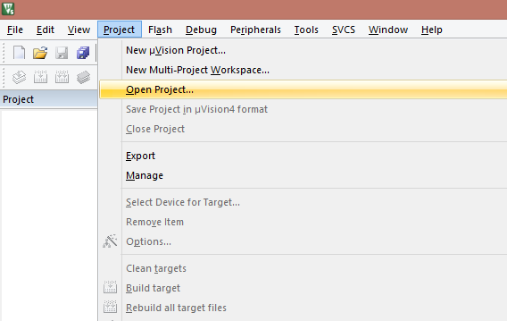
Run Keil and click Project -> Open Project
Step 2
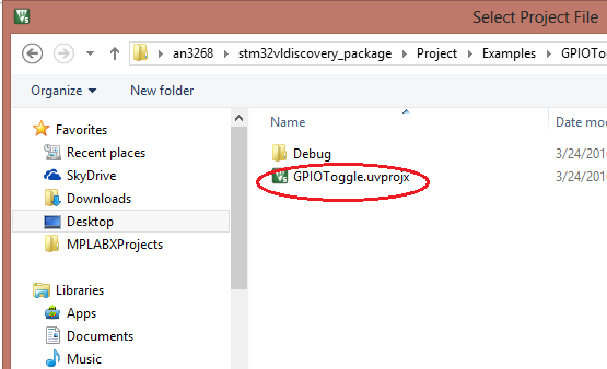
Locate the firmware package you've downloaded. Open the folder: \stm32vldiscovery_package\Project\Examples\GPIOToggle\MDK-ARM. Here you will find the file shown in the picture:
Step 3
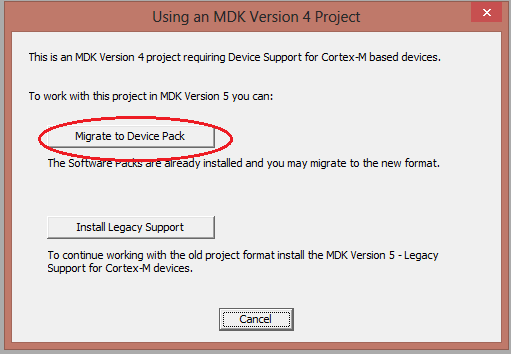
If your Keil is version 5 like me, a dialog box will appear like the one below. Just press the "Migrate to Device Pack" button. This will download the necessary files for the example project.
Step 4
After that, you can now see the main.c file on the User folder via the Project Explorer sidebar. If you're like me who is entirely a beginner with ARM programming, you'll be overwhelmed with the code. A lot would say that the learning curve for ARM programming is very steep as compared to PIC or Arduino programming. But I'll tell you, you will get the hang of it if you spend more time with it.
The next we'll do is we will replace the entire contents of the main.c file with code that is much more beginner friendly (github link):
#include "stm32f10x.h"
#include "stm32f10x_rcc.h"
#include "stm32f10x_gpio.h"

GPIO_InitTypeDef GPIO_InitStruct;
void delay(int a);

int main(void)
{
  // Enable clock for GPIOB
  RCC_APB2PeriphClockCmd(RCC_APB2Periph_GPIOB, ENABLE);
  // Configure PB0 as open-drain output
  GPIO_InitStruct.GPIO_Pin = GPIO_Pin_0;
  GPIO_InitStruct.GPIO_Speed = GPIO_Speed_2MHz;
  GPIO_InitStruct.GPIO_Mode = GPIO_Mode_Out_OD;
  GPIO_Init(GPIOB, &GPIO_InitStruct);
  while (1)
  {
    // Turn on LED on PB0 (LED circuit is active low)
    GPIO_ResetBits(GPIOB, GPIO_Pin_0);
    delay(500000);
    // Turn off LED on PB0
    GPIO_SetBits(GPIOB, GPIO_Pin_0);
    delay(500000);
  }
}

void delay (int a)
{
  volatile int i,j;
  for (i=0 ; i < a ; i++)
  {
    j++;
  }
  return;
}
Step 5
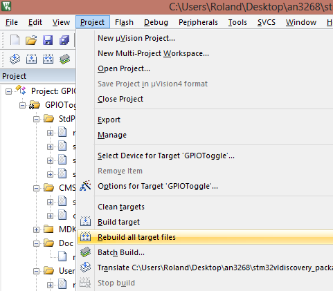
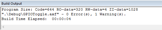
It's time to build the code! Go to Project -> Rebuild All Target Files
If everything is good, you should see this in the Build Output window:
Step 6
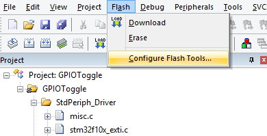
The next step is to download the program to the board. Before that, click on Flash -> Configure Flash Tools... first
By this time, your board should be already connected to your computer via USB. Click the Utilities tab and change the target driver for device programming to ST-Link Debugger.

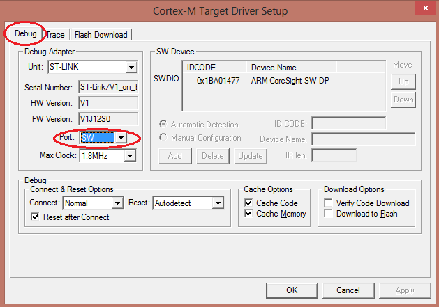
Next, press the Settings button and click on the Debug tab. Find the port option and change it to SW.
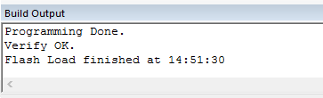
Press OK to close the dialog box and now you're ready to burn the program to your board. Press Flash and Download (F8) and you should see something written on the Build Output window. If everything's OK, this should be the last message shown:
Step 7
So what was that program we just loaded to the board? It's a simple blink program that blinks a LED connected to PBO. To see the code in action, connect a LED to PBO like this:

Oh, you also need to press the reset button on the board after loading the program. After that, the LED should be blinking.
Explaining the Code
Headers
I'll start with this part here:
#include "stm32f10x.h"
#include "stm32f10x_rcc.h"
#include "stm32f10x_gpio.h"

GPIO_InitTypeDef GPIO_InitStruct;
void delay(int a);
We needed three header files in order for this to work: the main header file (stm32f10x.h), the peripheral clock header file (stm32f10x_rcc.h) and the gpio header file (stm32f10x_gpio.h).
To access the GPIOs, we need to instantiate a GPIO_InitTypeDef class and name it GPIO_InitStruct. We also initiate our delay function here as we used it after the main function (which would result in a compiler error if we didn't).
Main Function
int main(void)
{
 // Enable clock for GPIOB
 RCC_APB2PeriphClockCmd(RCC_APB2Periph_GPIOB, ENABLE);
 // Configure PB0 as open-drain output
 GPIO_InitStruct.GPIO_Pin = GPIO_Pin_0;
 GPIO_InitStruct.GPIO_Speed = GPIO_Speed_2MHz;
 GPIO_InitStruct.GPIO_Mode = GPIO_Mode_Out_OD;
 GPIO_Init(GPIOB, &GPIO_InitStruct);
 while (1)
 {
  // Turn on LED on PB0 (LED circuit is active low)
  GPIO_ResetBits(GPIOB, GPIO_Pin_0);
  delay(500000);
  // Turn off LED on PB0
  GPIO_SetBits(GPIOB, GPIO_Pin_0);
  delay(500000);
 }
}
As it turns out, you need to enable the clock of the STM32F1 discovery's peripheral because they are not enabled at power on. (This was weird for me being a PIC and Arduino guy where the GPIO peripheral don't need any clock setting). This is what
RCC_APB2PeriphClockCmd(RCC_APB2Periph_GPIOB, ENABLE);
does.
Next, you need to specify and configure the GPIO you will be using. This is done via the functions under the GPIO_InitStruct class. The GPIO_Init() handles which GPIO port to use and loads the GPIO_InitStruct settings declared.
GPIO_InitStruct.GPIO_Pin = GPIO_Pin_0;
GPIO_InitStruct.GPIO_Speed = GPIO_Speed_2MHz;
GPIO_InitStruct.GPIO_Mode = GPIO_Mode_Out_OD;
GPIO_Init(GPIOB, &GPIO_InitStruct);
The blinking is done via the functions GPIO_ResetBits() and GPIO_SetBits() which takes the GPIO port and GPIO pin as arguments:
while (1)
{
 // Turn on LED on PB0 (LED circuit is active low)
 GPIO_ResetBits(GPIOB, GPIO_Pin_0);
 delay(500000);
 // Turn off LED on PB0
 GPIO_SetBits(GPIOB, GPIO_Pin_0);
 delay(500000);
}
Let’s Delay Things
Finally, the last part of the code is the delay function. It increments variable i until it reaches the value of the passed argument a. For example, if the value of a is 500000 then it would take this function would count to 500000, keeping the CPU busy, thus a delay .
void delay (int a)
{
 volatile int i,j;
 for (i=0 ; i < a ; i++)
 {
  j++;
 }
 return;
}
Summary
Let's summarize all the things you need to do to program the STM32F1:
- First, download Keil
- Second, download the STM32 Discovery Package
- Third, follow the steps outlined in this tutorial
- Fourth, load the example blink code
- Fifth and finally, download the code to the STM32 board
So that's it! I'll be doing a full-pledge STM32F1 discovery tutorial in the future. In the mean time, if you have any questions or reactions, just leave a comment below. Good luck!


")


Thank you. Nice explanatin !!