Using a keypad is an upgrade over using buttons for input on your Arduino project. Actually, a keypad is a set of 12 or 16 buttons wired so that the pin usage is reduced. In this tutorial, I will explain how a keypad matrix works and how to use it with an Arduino.
Buttons vs. Keypads
As shown in my Arduino led control tutorial, one push button usually needs one Arduino input pin:
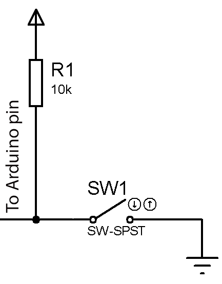
So, if your project needs 16 buttons, you may need 16 Arduino pins. A keypad matrix solves this problem by wiring the buttons in rows and columns instead.
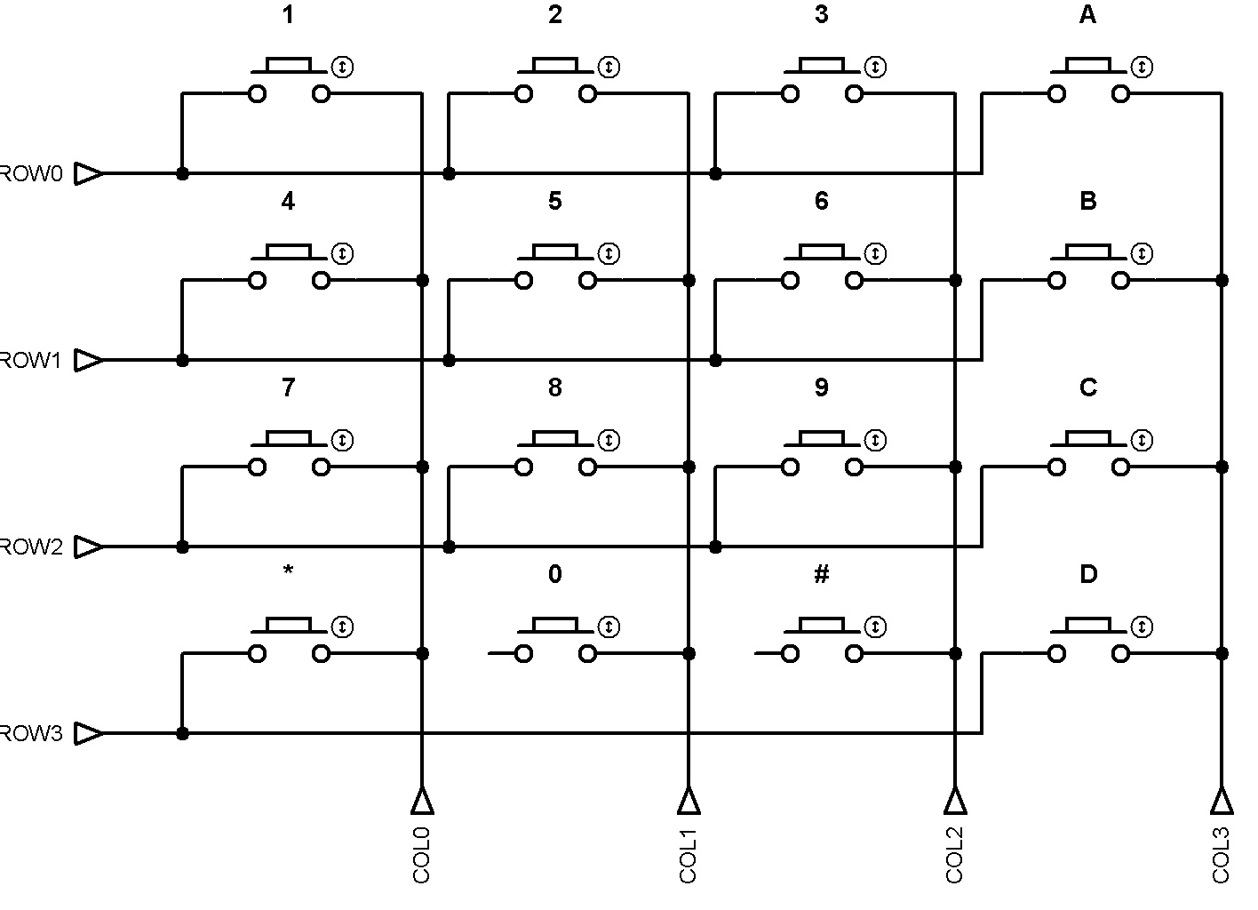
A 4x4 keypad matrix has 8 pins divided into 4 rows and 4 columns. When you press a button, that button connects one row pin to one column pin. For example, pressing button “1” connects row “0” to column “0”.
How a Keypad Matrix Works
To read a keypad matrix with an Arduino, you need to find which row and column connect when the user presses a key.
This sounds simple, but the Arduino must scan the keypad continuously. The common method uses one column pin at a time. The Arduino sets one column HIGH, keeps the other columns LOW, and then checks the row pins. After that, it moves to the next column and repeats the process.
Think of it like an LED chaser, but instead of lighting LEDs, the Arduino checks each column one by one.
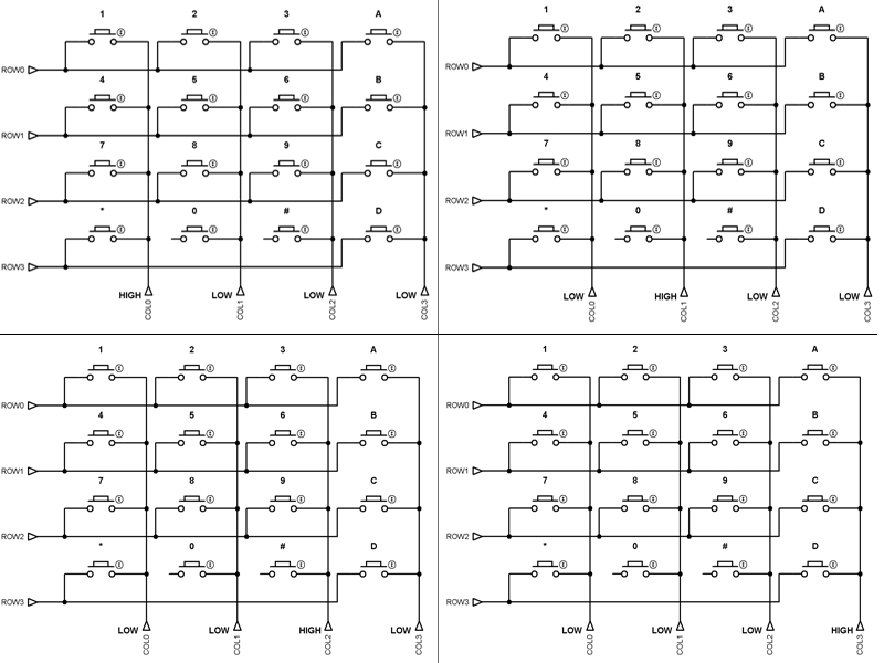
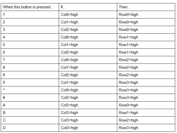
For example, look at the first image in the panel above. Column “0” goes HIGH while the other columns stay LOW. If you press button “1”, row “0” also goes HIGH because button “1” connects row “0” to column “0”. So, when the Arduino reads row “0” as HIGH while column “0” is HIGH, it knows that the user pressed button “1”. To detect all buttons, the Arduino scans every column and checks every row. You can summarize the process like this:
Keypad Scanning Arduino Sketch
Now we can implement the scanning technique I described above on an Arduino sketch. By the way, I’ll be using this 4x4 matrix keypad for this example and the rest of this article:
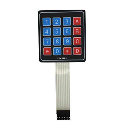
To continue, we will use this wiring diagram:
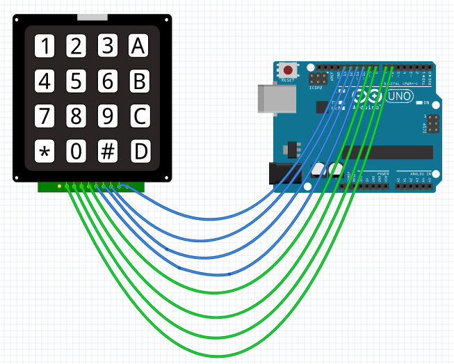
Here, the rows are connected to digital pins 10 to 13 while the columns pins are connected to digital pins 6 to 9.
Arduino Keypad Code
Here is the Arduino sketch:
int ROWS[4] = {10,11,12,13};
int COLS[4] = {6,7,8,9};

void setup() {
  // put your setup code here, to run once:
  //Make column pins output
  pinMode(6, OUTPUT);
  pinMode(7, OUTPUT);
  pinMode(8, OUTPUT);
  pinMode(9, OUTPUT);
  //Make row pins input
  pinMode(10, INPUT);
  pinMode(11, INPUT);
  pinMode(12, INPUT);
  pinMode(13, INPUT);

  Serial.begin(9600); //For printing out the output
}

void loop() {
  // put your main code here, to run repeatedly:
  digitalWrite(COLS[0],HIGH);
  digitalWrite(COLS[1],LOW);
  digitalWrite(COLS[2],LOW);
  digitalWrite(COLS[3],LOW);

  if(digitalRead(ROWS[0]) == HIGH && digitalRead(ROWS[1]) == LOW && digitalRead(ROWS[2]) == LOW && digitalRead(ROWS[3]) == LOW){
        Serial.println("1");
  }else if(digitalRead(ROWS[0]) == LOW && digitalRead(ROWS[1]) == HIGH && digitalRead(ROWS[2]) == LOW && digitalRead(ROWS[3]) == LOW){
        Serial.println("4");
  }else if(digitalRead(ROWS[0]) == LOW && digitalRead(ROWS[1]) == LOW && digitalRead(ROWS[2]) == HIGH && digitalRead(ROWS[3]) == LOW){
        Serial.println("7");
  }else if(digitalRead(ROWS[0]) == LOW && digitalRead(ROWS[1]) == LOW && digitalRead(ROWS[2]) == LOW && digitalRead(ROWS[3]) == HIGH){
        Serial.println("*");
  }else{;}
  delay(100);

  digitalWrite(COLS[0],LOW);
  digitalWrite(COLS[1],HIGH);
  digitalWrite(COLS[2],LOW);
  digitalWrite(COLS[3],LOW);

  if(digitalRead(ROWS[0]) == HIGH && digitalRead(ROWS[1]) == LOW && digitalRead(ROWS[2]) == LOW && digitalRead(ROWS[3]) == LOW){
        Serial.println("2");
  }else if(digitalRead(ROWS[0]) == LOW && digitalRead(ROWS[1]) == HIGH && digitalRead(ROWS[2]) == LOW && digitalRead(ROWS[3]) == LOW){
        Serial.println("5");
  }else if(digitalRead(ROWS[0]) == LOW && digitalRead(ROWS[1]) == LOW && digitalRead(ROWS[2]) == HIGH && digitalRead(ROWS[3]) == LOW){
        Serial.println("8");
  }else if(digitalRead(ROWS[0]) == LOW && digitalRead(ROWS[1]) == LOW && digitalRead(ROWS[2]) == LOW && digitalRead(ROWS[3]) == HIGH){
        Serial.println("0");
  }else{;}
  delay(100);

  digitalWrite(COLS[0],LOW);
  digitalWrite(COLS[1],LOW);
  digitalWrite(COLS[2],HIGH);
  digitalWrite(COLS[3],LOW);

  if(digitalRead(ROWS[0]) == HIGH && digitalRead(ROWS[1]) == LOW && digitalRead(ROWS[2]) == LOW && digitalRead(ROWS[3]) == LOW){
        Serial.println("3");
  }else if(digitalRead(ROWS[0]) == LOW && digitalRead(ROWS[1]) == HIGH && digitalRead(ROWS[2]) == LOW && digitalRead(ROWS[3]) == LOW){
        Serial.println("6");
  }else if(digitalRead(ROWS[0]) == LOW && digitalRead(ROWS[1]) == LOW && digitalRead(ROWS[2]) == HIGH && digitalRead(ROWS[3]) == LOW){
        Serial.println("9");
  }else if(digitalRead(ROWS[0]) == LOW && digitalRead(ROWS[1]) == LOW && digitalRead(ROWS[2]) == LOW && digitalRead(ROWS[3]) == HIGH){
        Serial.println("#");
  }else{;}
  delay(100);

  digitalWrite(COLS[0],LOW);
  digitalWrite(COLS[1],LOW);
  digitalWrite(COLS[2],LOW);
  digitalWrite(COLS[3],HIGH);

  if(digitalRead(ROWS[0]) == HIGH && digitalRead(ROWS[1]) == LOW && digitalRead(ROWS[2]) == LOW && digitalRead(ROWS[3]) == LOW){
        Serial.println("A");
  }else if(digitalRead(ROWS[0]) == LOW && digitalRead(ROWS[1]) == HIGH && digitalRead(ROWS[2]) == LOW && digitalRead(ROWS[3]) == LOW){
        Serial.println("B");
  }else if(digitalRead(ROWS[0]) == LOW && digitalRead(ROWS[1]) == LOW && digitalRead(ROWS[2]) == HIGH && digitalRead(ROWS[3]) == LOW){
        Serial.println("C");
  }else if(digitalRead(ROWS[0]) == LOW && digitalRead(ROWS[1]) == LOW && digitalRead(ROWS[2]) == LOW && digitalRead(ROWS[3]) == HIGH){
        Serial.println("D");
  }else{;}
  delay(100);
}
Using the Keypad Library
The sketch above is quite long. Isn’t there a quicker way? Yes, there is and that’s by using the official Arduino Keypad library.
Although it’s official, the Keypad library is not installed on the IDE by default. To install the library, go to Sketch > Include Library > Manage Libraries. Type “keypad” on the search box and locate the library by Mark Stanley and Alexander Brevig.
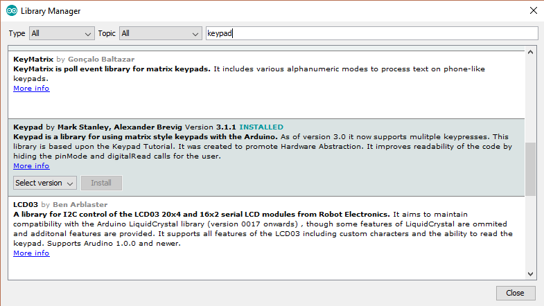
Once installed, the Keypad folder should now appear on the examples menu. There are a lot of examples provided in this folder. Here is the CustomKeyboard sketch:
#include <Keypad.h>

const byte ROWS = 4; //four rows
const byte COLS = 4; //four columns

//define the cymbols on the buttons of the keypads
char hexaKeys[ROWS][COLS] = {
  {'1','2','3','A'},
  {'4','5','6','B'},
  {'7','8','9','C'},
  {'*','0','#','D'}
};

byte rowPins[ROWS] = {10, 11, 12, 13}; //connect to the row pinouts of the keypad
byte colPins[COLS] = {6, 7, 8, 9}; //connect to the column pinouts of the keypad

//initialize an instance of class NewKeypad
Keypad customKeypad = Keypad( makeKeymap(hexaKeys), rowPins, colPins, ROWS, COLS);

void setup(){
  Serial.begin(9600);
}

void loop(){
  char customKey = customKeypad.getKey();
  if (customKey){
        Serial.println(customKey);
  }
}
I’ve modified the sketch to fit the wiring diagram we have above. The output of this sketch is the same as the longer sketch I’ve previously gave.
The above sketch is way shorter than the one I’ve provided. And since you can create a Keypad class using the library, you can even make multiple keypads, provided your Arduino still have available pins. I highly recommend using this Keyboard library.
Using Fewer Pins with Keypad Matrix
There is another way to use the 4x4 keypad matrix without using 8 Arduino pins. In fact, you’ll only be using one pin! All you need is wire the matrix like this:
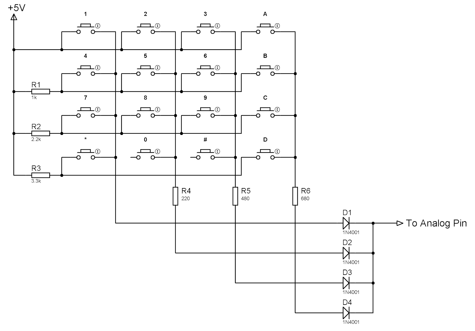
Using the schematic above, when a button is pressed, a different voltage level is read on the output pin. For example, if button “4” is pressed, current will flow from the +5V source, through the 1k resistor and through the diode. The voltage at the output will be

If button “8” is pressed, the current will flow through the 2.2K and 220 resistors, giving a different voltage at the output and so on.
The downside of using this method is you have to test each button and acquire their output voltage as computations will be different from the actual value. Use the built-in AnalogReadSerial example (Files > Examples > 01. Basics > AnalogReadSerial) for testing while connecting the output pin in the schematic above to A0.
Using an Arduino Keypad 4x3 Matrix
If you own the 4x3 keypad matrix instead of the 4x4 featured in this tutorial, you can still use the same example sketches presented here. Just remove the fourth column!
I hope you learned something from this Arduino Keypad tutorial. For updates on more tutorials like this, subscribe to this website (on the sidebar) or keep checking out this website! Have fun building!