
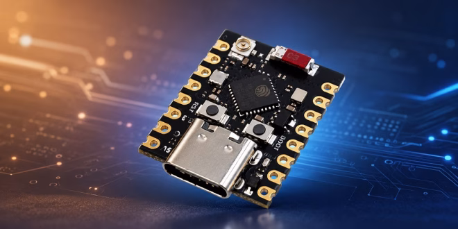
The ESP32-C3 Super Mini is one of those tiny development boards that looks almost too small to be useful at first. But once you plug it in and get past the first upload, it becomes a very handy board for compact Wi-Fi and BLE projects. It is smaller than the usual ESP32 DevKit board, it uses USB-C on most versions, and it can run Arduino sketches without much trouble. The only catch is that the ESP32-C3 Super Mini pinout can be a little confusing because some pins have boot functions, some are used by the onboard LED, and some online pinout diagrams do not always agree with each other.
In this guide, I will walk you through the important parts: what the board is, which Arduino IDE board option to select, how to upload your first sketch, which pins are safe to use, and how to blink the ESP32-C3 Super Mini built-in LED pin.
If your board was sold as a Core ESP32-C3 board for Arduino, this guide should still help. Most of those small boards use the same ESP32-C3 chip and work with the same Arduino core.
What Is the ESP32-C3 Super Mini?
The ESP32-C3 Super Mini is a small development board based on Espressif’s ESP32-C3 microcontroller. Unlike the older and more common ESP32 boards, the ESP32-C3 does not use the dual-core Xtensa processor. Instead, it uses a single-core 32-bit RISC-V processor. For most Arduino projects, this difference is not something you need to worry about right away. Your digital outputs, analog inputs, Wi-Fi sketches, web servers, and sensor projects still work in the same familiar Arduino style.
The board gives you:
- Wi-Fi
- Bluetooth Low Energy
- Digital input and output pins
- PWM
- Analog inputs
- I2C
- SPI
- UART
- Native USB programming
- A very small footprint
That combination makes it useful for compact IoT projects, sensor nodes, Wi-Fi buttons, BLE beacons, and small battery-powered experiments.
Why Use the ESP32-C3 Super Mini?
The biggest advantage is size. A full-size ESP32 DevKit board is easier to handle, but it takes up more space on a breadboard or inside an enclosure. The ESP32-C3 Super Mini gives you the main ESP32 features in a much smaller board.
I would use this board when:
- The project needs Wi-Fi but space is limited.
- I want a cheap board for a small sensor node.
- I need BLE but not Bluetooth Classic.
- I want something smaller than an ESP32 DevKit.
- I want a board that can plug directly into USB-C.
However, I would not use it as my very first ESP32 board if I had no experience at all. The pins are closer together, the labeling can vary between sellers, and some GPIO pins have special boot behavior. It is still beginner-friendly, but you need to pay attention to the pinout.
ESP32-C3 Super Mini Specifications
Here are the typical specifications of an ESP32-C3 Super Mini board:
| Feature | Typical Value |
|---|---|
| Microcontroller | ESP32-C3 |
| CPU | 32-bit RISC-V single-core |
| Clock Speed | Up to 160 MHz |
| Wireless | 2.4 GHz Wi-Fi and Bluetooth LE |
| SRAM | 400 KB |
| ROM | 384 KB |
| Flash | Usually 4 MB |
| Logic Level | 3.3V |
| USB | Native USB through USB-C |
| ADC Pins | GPIO0 to GPIO5 |
| Built-in LED | Usually GPIO8 |
| Buttons | BOOT and RESET |
The flash size is usually 4 MB, but it is still worth checking your specific board. Some online listings reuse the same photos for slightly different versions.
ESP32-C3 Super Mini Board Layout
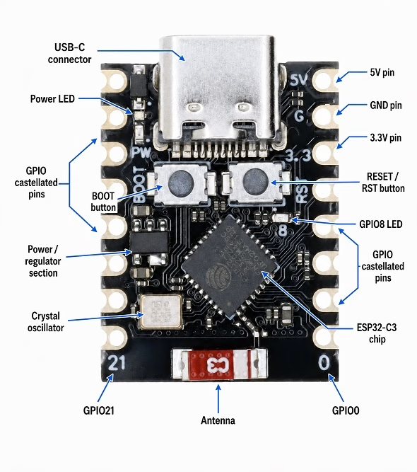
Most ESP32-C3 Super Mini boards have a USB-C connector on one end and the antenna on the other end. You will usually find two small buttons on the board:
- BOOT button
- RESET button
The BOOT button is useful when the board does not automatically enter upload mode. The RESET button simply restarts the board. You may also see a small LED near the center or side of the board. On many ESP32-C3 Super Mini boards, this LED is connected to GPIO8. This is the LED we will test later. One important layout note: keep the antenna area clear. Avoid placing metal parts, large wires, batteries, or copper areas directly under the antenna side of the board. The board may still work, but Wi-Fi range can suffer.
ESP32-C3 Super Mini Pinout
The exact ESP32-C3 Super Mini pinout can vary slightly depending on the manufacturer, but most boards expose a similar group of pins.
A common pinout looks like this:
| Board Label | GPIO | Common Use |
|---|---|---|
| 5V | - | 5V from USB or 5V input |
| GND | - | Ground |
| 3V3 | - | 3.3V output |
| 0 | GPIO0 | Digital I/O, ADC, PWM |
| 1 | GPIO1 | Digital I/O, ADC, PWM |
| 2 | GPIO2 | Digital I/O, ADC, PWM, strapping pin |
| 3 | GPIO3 | Digital I/O, ADC, PWM |
| 4 | GPIO4 | Digital I/O, ADC, PWM |
| 5 | GPIO5 | Digital I/O, ADC, PWM |
| 6 | GPIO6 | Digital I/O, PWM |
| 7 | GPIO7 | Digital I/O, PWM |
| 8 | GPIO8 | Digital I/O, often built-in LED |
| 9 | GPIO9 | Digital I/O, BOOT-related pin |
| 10 | GPIO10 | Digital I/O, PWM |
| 20 | GPIO20 | UART RX / GPIO |
| 21 | GPIO21 | UART TX / GPIO |
Some boards also print SDA and SCL labels beside GPIO8 and GPIO9. That does not mean you must always use those pins for I2C. On the ESP32-C3, you can usually assign I2C to different GPIO pins in your code.
Pins You Should Be Careful With
This is the part that many beginners miss. Some ESP32-C3 pins are strapping pins. The chip checks these pins while booting. If your external circuit pulls one of these pins to the wrong level during reset, the board may fail to boot or fail to upload.
Be careful with these pins:
| Pin | Why It Needs Care |
|---|---|
| GPIO2 | Strapping pin |
| GPIO8 | Strapping pin and often built-in LED |
| GPIO9 | Strapping pin and usually connected to BOOT |
| GPIO18 / GPIO19 | Used for native USB on many ESP32-C3 boards |
This does not mean you can never use these pins. You can. But for your first projects, it is better to start with less troublesome pins.
Best GPIO Pins for Beginner Projects
For simple LEDs, buttons, sensors, and digital outputs, I would start with:
- GPIO0
- GPIO1
- GPIO3
- GPIO4
- GPIO5
- GPIO6
- GPIO7
- GPIO10
For analog input, use:
- GPIO0
- GPIO1
- GPIO2
- GPIO3
- GPIO4
- GPIO5
For UART, many boards use:
- GPIO20 = RX
- GPIO21 = TX
For the built-in LED, try: GPIO8
If GPIO8 does not work on your board, try GPIO10. Some clone boards use a different LED pin.
Powering the ESP32-C3 Super Mini
The easiest way to power the board is through the USB-C connector.
You may also see 5V, 3V3, and GND pins on the board.
Here is what they mean:
- 5V is usually connected to the USB 5V line.
- 3V3 is the regulated 3.3V supply.
- GND is ground.
The ESP32-C3 itself is a 3.3V device. Its GPIO pins are not 5V tolerant. Do not connect a 5V signal directly to any GPIO pin. This is especially important when using modules like relays, ultrasonic sensors, or some older 5V Arduino modules. If a module outputs 5V, use a level shifter or voltage divider before connecting it to the ESP32-C3.
Installing ESP32-C3 Support in Arduino IDE
To program the ESP32-C3 Super Mini with Arduino IDE, you need to install the ESP32 board package.
Open Arduino IDE, then go to:
File > Preferences
Find Additional Boards Manager URLs and add this URL:
https://espressif.github.io/arduino-esp32/package_esp32_index.json
Then go to:
Tools > Board > Boards Manager
Search for: esp32
Then, install the package named: esp32 by Espressif Systems
After installation, restart Arduino IDE.
Which Board Should You Select?
For most ESP32-C3 Super Mini boards, select:
Tools > Board > esp32 > ESP32C3 Dev Module
This is the board option I would try first if your board is listed online as an ESP32-C3 Super Mini or Core ESP32-C3 board for Arduino.
Use these settings as a starting point:
| Arduino IDE Setting | Value |
|---|---|
| Board | ESP32C3 Dev Module |
| USB CDC On Boot | Enabled |
| CPU Frequency | 160 MHz |
| Flash Size | 4MB |
| Upload Speed | 921600 |
| Port | Select the detected USB port |
The most important setting here is USB CDC On Boot. If this is disabled, your sketch may upload, but the Serial Monitor may not show anything through USB. If upload fails at 921600, lower the upload speed to 460800 or 115200.
First Sketch: Check If the Board Is Working
Before connecting sensors or LEDs, upload a simple serial test sketch.
void setup() {
  Serial.begin(115200);
  delay(2000);

  Serial.println();
  Serial.println("ESP32-C3 Super Mini test");

  Serial.print("Chip model: ");
  Serial.println(ESP.getChipModel());

  Serial.print("Chip revision: ");
  Serial.println(ESP.getChipRevision());

  Serial.print("CPU frequency: ");
  Serial.print(ESP.getCpuFreqMHz());
  Serial.println(" MHz");

  Serial.print("Flash size: ");
  Serial.print(ESP.getFlashChipSize() / (1024 * 1024));
  Serial.println(" MB");
}

void loop() {
  Serial.println("Board is running...");
  delay(1000);
}
Upload the sketch, then open the Serial Monitor at: 115200 baud. If you see the board information and the “Board is running...” message, your Arduino IDE setup is working. If you see nothing, press RESET once. Also check that USB CDC On Boot is enabled.
If Upload Does Not Work
Some ESP32-C3 Super Mini boards enter upload mode automatically. Others are a little stubborn.
If Arduino IDE gets stuck at “Connecting...”, try this:
- Click Upload.
- When you see “Connecting...”, hold the BOOT button.
- Release BOOT once the upload starts.
If that still does not work, hold BOOT, tap RESET, then try uploading again. Also check the USB cable. A surprising number of upload problems are caused by charge-only USB-C cables.
ESP32-C3 Super Mini Built-In LED Pin
On many ESP32-C3 Super Mini boards, the built-in LED is connected to GPIO8. This LED is usually active LOW. That means the logic feels backward:
LOW = LED ON
HIGH = LED OFF
Upload this sketch to test the onboard LED:
#define LED_PIN 8

void setup() {
  pinMode(LED_PIN, OUTPUT);
}

void loop() {
  digitalWrite(LED_PIN, LOW);   // Turn LED ON
  delay(500);

  digitalWrite(LED_PIN, HIGH);  // Turn LED OFF
  delay(500);
}
If the onboard LED blinks, your board uses GPIO8 for the built-in LED. If nothing happens, try GPIO10:
#define LED_PIN 10
Some boards only have a power LED. If the LED turns on whenever the board is powered and never responds to your sketch, then it may not be connected to a GPIO pin.
Why the Built-In LED Pin Can Be Annoying
GPIO8 is convenient because it is often connected to the onboard LED. However, GPIO8 is also a strapping pin. For a simple blink test, this is not a big problem. But if you connect an external circuit to GPIO8, especially a circuit with a pull-up or pull-down resistor, it may affect the way the ESP32-C3 boots.
So here is the practical rule: Use GPIO8 for the onboard LED test. For external LEDs, buttons, and sensors, use another GPIO unless you have a reason to use GPIO8.
Testing Wi-Fi on the ESP32-C3 Super Mini
Once the board can upload sketches, the next useful test is Wi-Fi. The ESP32-C3 supports 2.4 GHz Wi-Fi. It does not connect to 5 GHz-only networks.
Upload this Wi-Fi scanner:
#include <WiFi.h>

void setup() {
  Serial.begin(115200);
  delay(2000);

  Serial.println();
  Serial.println("ESP32-C3 Wi-Fi scan");

  WiFi.mode(WIFI_STA);
  WiFi.disconnect();
  delay(100);

  int n = WiFi.scanNetworks();

  if (n == 0) {
    Serial.println("No networks found.");
  } else {
    Serial.print("Networks found: ");
    Serial.println(n);

    for (int i = 0; i < n; i++) {
      Serial.print(i + 1);
      Serial.print(": ");
      Serial.print(WiFi.SSID(i));
      Serial.print("  RSSI: ");
      Serial.print(WiFi.RSSI(i));
      Serial.println(" dBm");
      delay(10);
    }
  }
}

void loop() {
}
Open the Serial Monitor at 115200 baud. You should see nearby Wi-Fi networks. If the scan works, your Wi-Fi hardware is fine.
Connecting the ESP32-C3 Super Mini to Wi-Fi
Now try connecting to your router.
#include <WiFi.h>

const char* ssid = "YOUR_WIFI_NAME";
const char* password = "YOUR_WIFI_PASSWORD";

void setup() {
  Serial.begin(115200);
  delay(1000);

  Serial.println();
  Serial.print("Connecting to ");
  Serial.println(ssid);

  WiFi.begin(ssid, password);

  while (WiFi.status() != WL_CONNECTED) {
    delay(500);
    Serial.print(".");
  }

  Serial.println();
  Serial.println("Wi-Fi connected!");
  Serial.print("IP address: ");
  Serial.println(WiFi.localIP());
}

void loop() {
}
Replace the Wi-Fi name and password with your own network credentials. If the board keeps failing to connect, check that your network is 2.4 GHz. Many routers combine 2.4 GHz and 5 GHz under one network name, which usually works, but a 5 GHz-only network will not.
Simple Web Server LED Control
Here is a small web server example that controls the built-in LED from a browser. This sketch assumes the onboard LED is on GPIO8 and active LOW.
#include <WiFi.h>
#include <WebServer.h>

const char* ssid = "YOUR_WIFI_NAME";
const char* password = "YOUR_WIFI_PASSWORD";

#define LED_PIN 8

WebServer server(80);

bool ledOn = false;

void handleRoot() {
  String html = "<!DOCTYPE html><html>";
  html += "<head>";
  html += "<meta name='viewport' content='width=device-width, initial-scale=1'>";
  html += "<style>";
  html += "body{font-family:Arial;text-align:center;margin-top:40px;}";
  html += "button{font-size:24px;padding:12px 24px;margin:10px;}";
  html += "</style>";
  html += "</head>";

  html += "<body>";
  html += "<h1>ESP32-C3 Super Mini LED</h1>";
  html += "<p>LED is ";
  html += ledOn ? "ON" : "OFF";
  html += "</p>";
  html += "<p><a href='/on'><button>ON</button></a></p>";
  html += "<p><a href='/off'><button>OFF</button></a></p>";
  html += "</body></html>";

  server.send(200, "text/html", html);
}

void handleOn() {
  ledOn = true;
  digitalWrite(LED_PIN, LOW);   // active-low LED ON
  handleRoot();
}

void handleOff() {
  ledOn = false;
  digitalWrite(LED_PIN, HIGH);  // active-low LED OFF
  handleRoot();
}

void setup() {
  Serial.begin(115200);
  delay(1000);

  pinMode(LED_PIN, OUTPUT);
  digitalWrite(LED_PIN, HIGH);  // start with LED OFF

  Serial.println();
  Serial.print("Connecting to ");
  Serial.println(ssid);

  WiFi.begin(ssid, password);

  while (WiFi.status() != WL_CONNECTED) {
    delay(500);
    Serial.print(".");
  }

  Serial.println();
  Serial.println("Wi-Fi connected!");
  Serial.print("Open this address in your browser: http://");
  Serial.println(WiFi.localIP());

  server.on("/", handleRoot);
  server.on("/on", handleOn);
  server.on("/off", handleOff);

  server.begin();
}

void loop() {
  server.handleClient();
}
After uploading, open the Serial Monitor and copy the IP address. Open that address in a browser connected to the same Wi-Fi network. This is a good first “real” ESP32-C3 project because it tests USB, serial output, Wi-Fi, GPIO, and a simple web page.
Using I2C on the ESP32-C3 Super Mini
Many ESP32-C3 Super Mini pinout diagrams show GPIO8 as SDA and GPIO9 as SCL. That can work, but I do not always recommend it for beginners because those pins have special boot behavior. A safer approach is to define the I2C pins yourself.
For example, you can try GPIO6 and GPIO7:
#include <Wire.h>

#define SDA_PIN 6
#define SCL_PIN 7

void setup() {
  Serial.begin(115200);
  delay(1000);

  Wire.begin(SDA_PIN, SCL_PIN);

  Serial.println("Scanning I2C bus...");

  for (byte address = 1; address < 127; address++) {
    Wire.beginTransmission(address);
    byte error = Wire.endTransmission();

    if (error == 0) {
      Serial.print("I2C device found at 0x");
      if (address < 16) Serial.print("0");
      Serial.println(address, HEX);
    }
  }

  Serial.println("Scan complete.");
}

void loop() {
}
If your OLED display or sensor is already wired to the pins labeled SDA and SCL on your board, change the pin definitions to match those labels.
For example:
#define SDA_PIN 8
#define SCL_PIN 9
Just remember that GPIO8 and GPIO9 are not the safest pins for every circuit.
Reading an Analog Sensor
The ESP32-C3 has analog input pins on GPIO0 to GPIO5. Here is a simple potentiometer test using GPIO0:
#define POT_PIN 0

void setup() {
  Serial.begin(115200);
}

void loop() {
  int value = analogRead(POT_PIN);

  Serial.print("ADC value: ");
  Serial.println(value);

  delay(300);
}
Wire the potentiometer like this:
| Potentiometer Pin | ESP32-C3 Super Mini |
|---|---|
| One outer pin | 3V3 |
| Other outer pin | GND |
| Middle pin | GPIO0 |
Do not connect the potentiometer to 5V. The analog input pin should only receive a voltage between 0V and 3.3V.
Using UART on GPIO20 and GPIO21
Many ESP32-C3 Super Mini boards expose GPIO20 and GPIO21 as RX and TX. Typical wiring looks like this:
| ESP32-C3 Super Mini | External Serial Device |
|---|---|
| GPIO20 RX | TX |
| GPIO21 TX | RX |
| GND | GND |
Here is a simple UART bridge sketch:
HardwareSerial MySerial(1);

#define RX_PIN 20
#define TX_PIN 21

void setup() {
  Serial.begin(115200);
  MySerial.begin(9600, SERIAL_8N1, RX_PIN, TX_PIN);

  Serial.println("UART test started");
}

void loop() {
  if (MySerial.available()) {
    Serial.write(MySerial.read());
  }

  if (Serial.available()) {
    MySerial.write(Serial.read());
  }
}
This is useful when testing GPS modules, serial sensors, or other microcontrollers. Again, check voltage levels. The ESP32-C3 uses 3.3V logic.
Common Problems and Fixes
The Board Does Not Show Up in Arduino IDE
Try another USB cable first. Make sure it is a data cable, not just a charging cable.
Then try:
- Another USB port
- Pressing RESET
- Holding BOOT while plugging in the board
- Restarting Arduino IDE
- Checking whether the port appears in Device Manager or your operating system’s serial device list
Most ESP32-C3 Super Mini boards use native USB, so they usually do not need a separate CH340 or CP210x driver. But clone boards can vary.
Upload Gets Stuck at “Connecting...”
Put the board into bootloader mode manually:
- Hold BOOT.
- Click Upload.
- Release BOOT when upload starts.
If needed, hold BOOT, tap RESET, release RESET, then release BOOT.
Serial Monitor Is Blank
Check these settings:
- Serial Monitor baud rate is 115200.
- USB CDC On Boot is enabled.
- Correct port is selected.
- The sketch has
.Serial.begin(115200); - You added a short delay after
.Serial.begin()
This is one of the most common ESP32-C3 beginner issues.
The Built-In LED Does Not Blink
Try GPIO8 first, then GPIO10.
Also remember that many ESP32-C3 Super Mini boards use active-low LED wiring. So this turns the LED on:
digitalWrite(LED_PIN, LOW);
And this turns it off:
digitalWrite(LED_PIN, HIGH);
If the LED never responds, it may only be a power LED.
The Board Resets When Wi-Fi Starts
Wi-Fi needs short bursts of current. If the USB cable or port is weak, the board may reset when Wi-Fi turns on.
Try:
- A better USB cable
- A different USB port
- A powered USB hub
- Removing external loads from the 3.3V pin
- Powering external modules separately
Always connect grounds together when using an external power supply for sensors or modules.
Recommended First Projects
Once the board is working, these are good projects to try:
- Built-in LED blink
- Wi-Fi scanner
- Web server LED control
- OLED display using I2C
- BME280 weather monitor
- DHT22 temperature and humidity logger
- MQTT sensor node
- BLE beacon
- Deep sleep battery monitor
- UART GPS reader
The ESP32-C3 Super Mini is especially good for small connected projects where a full-size ESP32 board feels too large.
Frequently Asked Questions
What board should I select for ESP32-C3 Super Mini in Arduino IDE?
Select ESP32C3 Dev Module. This is the best starting option for most generic ESP32-C3 Super Mini boards.
Is the ESP32-C3 Super Mini compatible with Arduino?
Yes. Install the ESP32 board package by Espressif, then select ESP32C3 Dev Module in Arduino IDE.
What is the ESP32-C3 Super Mini built-in LED pin?
On many boards, the built-in LED is connected to GPIO8. It is usually active LOW, so writing LOW turns the LED on.
Why does my built-in LED not blink?
Your board may use a different LED pin, or the LED may only be a power indicator. Try GPIO8 first, then GPIO10.
Can I use GPIO8 and GPIO9?
Yes, but be careful. GPIO8 and GPIO9 are strapping pins. GPIO8 is often connected to the built-in LED, while GPIO9 is usually related to the BOOT button.
Can I connect 5V sensors to the ESP32-C3 Super Mini?
Only if the sensor output is 3.3V-compatible. The ESP32-C3 GPIO pins are not 5V tolerant. Use a level shifter when needed.
Does the ESP32-C3 support Bluetooth Classic?
No. The ESP32-C3 supports Bluetooth Low Energy, not Bluetooth Classic.
Can the ESP32-C3 Super Mini run MicroPython?
Yes. The board can run Arduino sketches, MicroPython, ESP-IDF projects, and PlatformIO projects. This guide focuses on Arduino IDE.
Conclusion
The ESP32-C3 Super Mini is a small but capable board for Wi-Fi and Bluetooth Low Energy projects. It is not as forgiving as a large ESP32 DevKit board because the pins are closer together and some GPIOs have boot functions, but it is still a very useful board once you understand the basics.
For a smooth start, remember these points:
- Select ESP32C3 Dev Module in Arduino IDE.
- Enable USB CDC On Boot.
- Use GPIO8 for the built-in LED on most boards.
- Remember that the built-in LED is usually active LOW.
- Be careful with GPIO2, GPIO8, and GPIO9.
- Do not connect 5V signals directly to any GPIO pin.
After you get the first blink and Wi-Fi test working, the ESP32-C3 Super Mini becomes a great board for compact IoT projects, web-controlled devices, and small wireless sensor builds.


