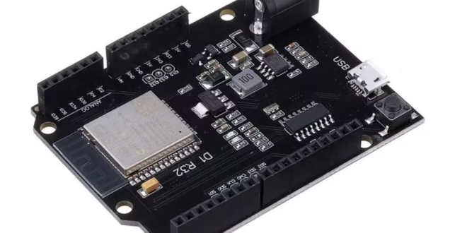
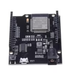
The WeMos D1 R32 is an ESP32-based development board that takes the familiar Arduino Uno form factor. It promises to give makers the power of the ESP32—Wi-Fi, Bluetooth, dual-core processing—while keeping the physical compatibility of an Arduino board.
But as many users have discovered, the D1 R32 isn’t a drop-in replacement for the Arduino Uno. It comes with its own quirks, voltage caveats, and pinout inconsistencies that can be confusing for beginners and even experienced developers. This guide will walk you through everything you need to know about the WeMos D1 R32 — its features, pinouts, and the oddities you should be aware of before integrating it into your next project.
Overview
The WeMos D1 R32 is essentially an ESP32 Dev Module reshaped into an Arduino Uno footprint. It’s a handy board if you want to upgrade an existing Arduino project to an ESP32 without redesigning your enclosure or layout.
| Specification | Details |
| Microcontroller | ESP32-WROOM-32 |
| CPU | Dual-core Tensilica Xtensa LX6 @ up to 240 MHz |
| Flash Memory | 4 MB |
| SRAM | 520 KB |
| Wi-Fi | 802.11 b/g/n |
| Bluetooth | Classic + BLE |
| Logic Level | 3.3 V |
| USB-Serial Chip | CH340 or CP2102 (varies by manufacturer) |
| Voltage Regulator | AMS1117-3.3 |
| Board Form Factor | Arduino UNO R3 layout |

Features at a Glance
- ESP32 microcontroller with integrated Wi-Fi and Bluetooth
- Dual-core processor for multitasking applications
- Arduino UNO-style headers for shield compatibility (with limitations)
- USB connection for programming and serial monitoring
- Onboard 3.3 V regulator and barrel jack for external power input
- Reset and EN buttons
Pinout Diagram
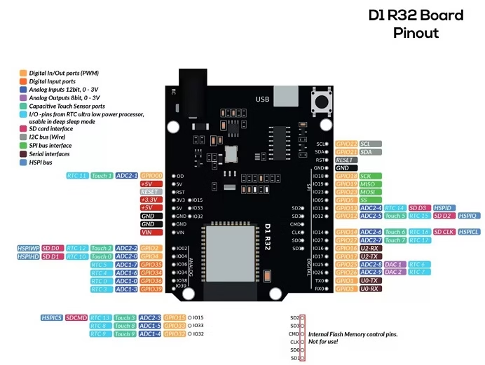 Note: Different manufacturers use slightly different silkscreen labels. Always confirm with a multimeter or schematic before wiring critical peripherals.
| Arduino Label | ESP32 GPIO | Function / Interface | Notes / Remarks |
|---|---|---|---|
| A0 | GPIO2 | ADC_LINE(0), LED, PWM_DEV(0):4 | Shared with onboard LED; also usable as analog input. |
| A1 | GPIO4 | ADC_LINE(1) | ADC channel. |
| A2 | GPIO35 | ADC_LINE(2) | ADC channel; input-only. |
| A3 | GPIO34 | ADC_LINE(3) | ADC channel; input-only. |
| A4 | GPIO36 | ADC_LINE(4) | ADC channel; input-only. |
| A5 | GPIO39 | ADC_LINE(5) | ADC channel; input-only. |
| D0 (RX) | GPIO3 | UART_DEV(0):RxD | Serial RX (connected to USB-serial bridge). |
| D1 (TX) | GPIO1 | UART_DEV(0):TxD | Serial TX (connected to USB-serial bridge). |
| D2 | GPIO26 | DAC_LINE(1), PWM_DEV(0):1 | DAC output & PWM capable. |
| D3 | GPIO25 | DAC_LINE(0), PWM_DEV(0):0 | DAC output & PWM capable. (D3 → GPIO25 — verified mapping.) |
| D4 | GPIO10 | UART_DEV(1):TxD | Secondary UART TX — may be unavailable on some modules (flash pins). |
| D5 | GPIO9 / GPIO16* | UART_DEV(1):RxD / PWM_DEV(0):1 | Depends on revision; GPIO9–10 are often flash pins and may be unavailable. Verify your board. |
| D6 | GPIO27 | PWM_DEV(0):2 | PWM capable. |
| D9 | GPIO13 | PWM_DEV(0):3 | PWM capable. |
| D10 | GPIO5 | SPI_DEV(0):CS0, PWM_DEV(1):0 | SPI chip-select / PWM output. |
| D11 | GPIO23 | SPI_DEV(0):MOSI, PWM_DEV(1):1 | SPI MOSI / PWM output. |
| D12 | GPIO19 | SPI_DEV(0):MISO | SPI MISO. |
| D13 | GPIO18 | SPI_DEV(0):CLK | SPI clock. |
| SDA | GPIO21 | I2C_DEV(0):SDA | I²C data (default bus). |
| SCL | GPIO22 | I2C_DEV(0):SCL | I²C clock (default bus). |
| LED_BUILTIN | GPIO2 | LED / PWM_DEV(0):4 | Onboard LED (same as A0 on many revisions). |
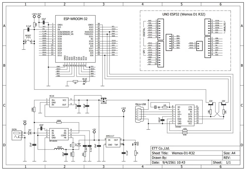
Schematic Diagram
Key Schematic Blocks
Power / Voltage Regulation
-
- The board accepts 5 V via USB micro-B (or via VIN barrel/5V pin) and uses onboard regulator (often AMS1117‐3.3 or equivalent) to generate 3.3 V for the ESP32.
- A diode or poly-fuse is often used between USB 5 V and board 5 V rail → this causes voltage drop under load. Some users observed 4.3-4.6 V on the 5 V rail under load.
- The barrel jack/Vin input may go through a switch/regulator network; some boards show trouble booting when powered only via barrel jack. (See quirks section)
- Important: The 3.3 V regulator must supply enough current for the ESP32 + WiFi peak bursts (~200-300 mA or more) + any attached modules. If the regulator is weak or overheats, the board may freeze or reset.
USB to Serial Interface
-
- The board uses a USB-serial bridge chip (typically CH340G) to handle USB programming/debug. The KIO4 schematic shows CH340C (or variant) connected to USB D+/D-, crystal, and to ESP32’s TX0/RX0.
- DTR/RTS lines may be connected (through capacitors) to the ESP32 EN & IO0 lines to allow auto-bootloader entry when uploading. On some clones this is poorly connected, causing problems.
ESP32 Module & Boot-strap Pins
-
- The schematic shows the ESP32-WROOM-32 module. It includes its antenna, flash memory, etc. The board then routes ESP32 pins to Arduino-style headers.
- Certain pins function as boot-straps: e.g., GPIO0, GPIO2, GPIO15, etc. The board schematic typically shows pull-ups or pull-downs on them. If an external device drives these incorrectly at startup, the ESP32 might not boot properly.
Header Pin Mapping
-
- The schematic shows how each header pin (Arduino form-factor) maps to the ESP32 GPIO. Because the board is not an ATmega based Uno, the mapping is custom. On the schematic you’ll see pin labels like IO25 → “D3” etc.
- It is critical to consult the board’s schematic or user-manual rather than assume D-pin names correspond exactly as with classic Arduino.
Other Circuits (Reset, EN, Buttons, LEDs)
-
- The schematic shows Reset button (RST) tied to ESP32 EN via resistor/capacitor network.
- On-board LED is usually connected to GPIO2 (on many versions) through a resistor. The schematic confirms LED to GPIO2.
- Some boards include power LED, USB activity LED, etc.
How to Program the WeMos D1 R32
Since the board isn’t officially listed in the Arduino IDE board list, you can program it as an ESP32 Dev Module: Install the ESP32 Arduino Core Go to:
File > Preferences > Additional Boards Manager URLs
Add:
https://dl.espressif.com/dl/package_esp32_index.json
Open Boards Manager, search for “ESP32”, and install the ESP32 by Espressif Systems package. Select the board:
Tools > Board > ESP32 Dev Module
Choose the correct COM port and upload your code. 💡 Tip: If upload fails, press and hold the BOOT button while the IDE says “Connecting…”, then release it when uploading starts.
Common Quirks and Peculiarities
Despite its appealing design, the D1 R32 has some notorious quirks that can make or break your project.
1. Unreliable 5 V Pin
Many users report that the 5 V pin outputs only 4.3–4.6 V, or even less when under load. This happens because of the diode drop and cheap regulators used on some clone boards. Symptoms:
- Wi-Fi drops or restarts
- Board freezing when powering external devices from 5V pin
- USB connection unstable
Recommendation: ✅ Use a dedicated 5 V power supply for external modules. ✅ Don’t draw heavy current (>200 mA) from the 5 V pin.
2. Barrel Jack Doesn’t Always Work
Some users report the board doesn’t boot when powered only via the barrel jack. The issue seems related to undervoltage or regulator startup. Fix: Use USB power or the 5 V pin instead, or ensure your adapter supplies at least 5.5 V.
3. UNO Shield Compatibility is Limited
While the board’s layout looks like an Arduino Uno, it’s not electrically compatible.
- The ESP32 uses 3.3 V logic, while most Uno shields use 5 V logic.
- Some shields (like motor drivers) expect 5 V signals and won’t work correctly.
- The SPI/I2C pin assignments differ.
Solution:
- Check shield voltage tolerance before connecting.
- Use level shifters if needed.
4. LED_BUILTIN May Not Work
In Arduino sketches, LED_BUILTIN isn’t always defined for this board. On most versions, the onboard LED is connected to GPIO2, so add this line:
#define LED_BUILTIN 2
5. Confusing Analog Labels
The board silk labels (A0, A1, etc.) don’t always correspond to the ESP32 ADC pins. For example, the printed A2 (IO36) may actually be connected to GPIO35. Double-check the schematic or use analog testing code to confirm ADC channels.
Example: Blink Sketch
#define LED_BUILTIN 2

void setup() {
    pinMode(LED_BUILTIN, OUTPUT);
}

void loop() {
   digitalWrite(LED_BUILTIN, HIGH);
   delay(500);
   digitalWrite(LED_BUILTIN, LOW);
   delay(500);
}
Connecting to Wi-Fi
#include <WiFi.h>

const char* ssid = "YourWiFi";
const char* password = "YourPassword";

void setup() {
    Serial.begin(115200);
    WiFi.begin(ssid, password);
    Serial.print("Connecting to WiFi");

    while (WiFi.status() != WL_CONNECTED) {
        delay(500);
        Serial.print(".");
    }

    Serial.println("\nConnected!");
    Serial.println(WiFi.localIP());
}

void loop() {}
Final Thoughts
The WeMos D1 R32 is a versatile and affordable ESP32 board that’s perfect for Wi-Fi and Bluetooth projects—as long as you understand its quirks. It’s not a perfect Arduino Uno replacement, but if you handle power properly and double-check pin mappings, it can serve as a reliable platform for IoT, automation, and embedded learning projects. If you’re coming from the Arduino Uno world, the D1 R32 is an exciting step up into ESP32 performance—just don’t expect plug-and-play compatibility.