
I believe what makes Arduino popular is how it makes microcontrollers easier to use. I remember the time when I have to spent hours coding a project and then spend money on programming hardware. Arduino has its limitations, but the platform helps create tons of electronic projects even for non-engineers.
Thus, I decided to create a series showing how the most common Arduino functions work. This is not only for greater insight but also to appreciate all the work that was done to make programming easier for a lot of people.
For the first part of the series, I will be looking at three essential functions for dealing with digital inputs: pinMode(), digitalRead() and digitalWrite().
Introduction
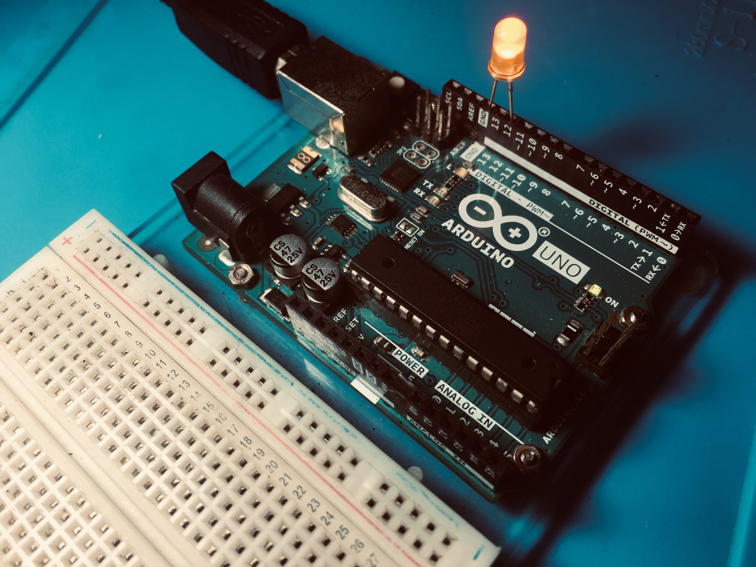
For brevity, I will choose only one out of the 19 current official Arduino board: the Arduino UNO. The UNO runs on Atmel’s ATMega328p chip, whose pinout is below:
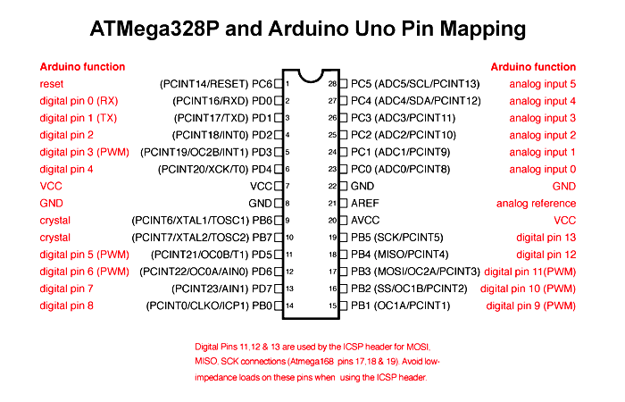
As seen here, each pin (except the power pins) is assigned to a port and a pin number. Starting from digital pin 0 to analog pin 5, PORTDs come first, then PORTBs and then PORTCs.
| No. | Arduino Pin Number | Port | No. | Arduino Pin Number | Port | No. | Arduino Pin Number | Port |
|---|---|---|---|---|---|---|---|---|
| 1 | D0 | PORTD | 9 | D8 | PORTB | 14 | A0 | PORTC |
| 2 | D1 | PORTD | 10 | D9 | PORTB | 15 | A1 | PORTC |
| 3 | D2 | PORTD | 11 | D10 | PORTB | 16 | A2 | PORTC |
| 4 | D3 | PORTD | 12 | D11 | PORTB | 17 | A3 | PORTC |
| 5 | D4 | PORTD | 13 | D12 | PORTB | 18 | A4 | PORTC |
| 6 | D5 | PORTD | D13 | PORTB | 19 | A5 | PORTC | |
| 7 | D6 | PORTD | Arduino pin numbers and corresponding ports, in sequence | |||||
| 8 | D7 | PORTD | ||||||
This sequence makes sense later on.
Say you want to use digital pin 13 (PB5) as an output pin and digital pin 5 (PD5) as an input pin. You would normally do this:
void setup(){
  pinMode(13, OUTPUT);
  pinMode(5, INPUT);
}

void loop(){
  digitalWrite(13, HIGH);
  int input = digitalRead(5);
}
From here on out, I will use this example sketch in our discussion.
The pinMode() Function
The pinMode() function accepts a pin number and mode as parameters:
void pinMode(uint8_t pin, uint8_t mode)
This function is inside wiring_digital.c which is found in <Your Installation Folder>\Arduino\hardware\arduino\avr\cores\arduino. The Arduino platform is based on Wiring, hence the name of the file.
Here’s the function in full:
void pinMode(uint8_t pin, uint8_t mode)
{
  uint8_t bit = digitalPinToBitMask(pin);
  uint8_t port = digitalPinToPort(pin);
  volatile uint8_t *reg, *out;

  if (port == NOT_A_PIN) return;

  // JWS: can I let the optimizer do this?

  reg = portModeRegister(port);
  out = portOutputRegister(port);

  if (mode == INPUT) {
    uint8_t oldSREG = SREG;
    cli();
    *reg &= ~bit;
    *out &= ~bit;
    SREG = oldSREG;
  } else if (mode == INPUT_PULLUP) {
    uint8_t oldSREG = SREG;
    cli();
    *reg &= ~bit;
    *out |= bit;
    SREG = oldSREG;
  } else {
    uint8_t oldSREG = SREG;
    cli();
    *reg |= bit;
    SREG = oldSREG;
  }
}
The pin Parameter
In the first two lines of the function, the eight-bit variables pin and mode are passed to macros digitalPinToBitMask and digitalPinToPort:
uint8_t bit = digitalPinToBitMask(pin);
uint8_t port = digitalPinToPort(pin);
Both of these macros are inside Arduino.h found inside <Your Installation Folder>\Arduino\hardware\arduino\avr\cores\arduino and are defined as:
#define digitalPinToPort(P)(pgm_read_byte( digital_pin_to_port_PGM + (P)))
#define digitalPinToBitMask(P)(pgm_read_byte(digital_pin_to_bit_mask_PGM + (P)))
Here, the parameter pin is passed to P which is then used to select an element from the arrays digital_pin_to_port_PGM and digital_pin_to_bit_mask_PGM. Both these arrays are stored inside the microcontrollers program memory as the pgm_read_byte() function suggests. This makes sense since the ATMega328p has a lot of flash memory space compared to its RAM.
The elements of these arrays are viewable in the file pins_arduino.h which is in <Your Installation Folder>\Arduino\hardware\arduino\avr\variants\<Your Arduino Model>. There are different pins_arduino.h files for different Arduino boards. For the UNO, this file is inside the “standard” folder.
Here’s how the digital_pin_to_port_PGM array looks like:
const uint8_t PROGMEM digital_pin_to_port_PGM[] = {
  PD, /* 0 */
  PD,
  PD,
  PD,
  PD,
  PD,
  PD,
  PD,
  PB, /* 8 */
  PB,
  PB,
  PB,
  PB,
  PB,
  PC, /* 14 */
  PC,
  PC,
  PC,
  PC,
  PC,
};
This 20-element array contains the ports of the ATMega328p pins following the same sequence in the table above. For example, doing this:
pinMode(13, OUTPUT)
passes a value 13 to the macro:
uint8_t port = digitalPinToPort(pin);
which is now the value of P here:
digitalPinToPort(P)(pgm_read_byte( digital_pin_to_port_PGM + (P)))
which now returns the 14th element (count starts at zero) from the array.
This means that the variable port is now equal to a constant “PB”. This is a an alias for values defined in Arduino.h:
#ifdef ARDUINO_MAIN
#define PA 1
#define PB 2
#define PC 3
#define PD 4
#define PE 5
#define PF 6
#define PG 7
#define PH 8
#define PJ 10
#define PK 11
#define PL 12
#endif
So “PB” is an alias for “2”. The others are there for Arduino boards with lots of ports and pins (the Arduino Mega contains up to PL).
Meanwhile, the array digital_pin_to_bit_mask_PGM has the following elements:
const uint8_t PROGMEM digital_pin_to_bit_mask_PGM[] = {
  _BV(0), /* 0, port D */
  _BV(1),
  _BV(2),
  _BV(3),
  _BV(4),
  _BV(5),
  _BV(6),
  _BV(7),
  _BV(0), /* 8, port B */
  _BV(1),
  _BV(2),
  _BV(3),
  _BV(4),
  _BV(5),
  _BV(0), /* 14, port C */
  _BV(1),
  _BV(2),
  _BV(3),
  _BV(4),
  _BV(5),
};
This also accepts the number 13 and, similar to digital_pin_to_port_PGM, will return the 14th element in the array, which is _BV(5).
_BV, short for bit value, is an AVR macro that sets a bit number in a byte. So _BV(5) in binary means:
0010 0000
where the 5th bit from the right, starting at zero is set. This is 0x20 in hexadecimal. So in this line
uint8_t bit = digitalPinToBitMask(pin);
The variable bit is equal to 0x20.
As you see, both digital_pin_to_port_PGM and digital_pin_to_mask_PGM contain 20 elements inside the array. So what happens if you pass a number beyond the number of array elements? For example, what happens if you do this:
pinMode(21, OUTPUT)
Since there’s nothing inside both arrays at position 21, these two will return with 0 bytes
uint8_t bit = digitalPinToBitMask(pin);
uint8_t port = digitalPinToPort(pin);
Also, the value 0 is conveniently assigned an alias inside Arduino.h
#define NOT_A_PIN 0
#define NOT_A_PORT 0
Hence, inside the pinMode() function, you will see this line:
if (port == NOT_A_PIN) return;
So passing a pin number beyond 20 bypasses pinMode() and will do nothing on the pins.
The mode Parameter
The mode can be INPUT, INPUT_PULLUP and OUTPUT and these are defined inside Arduino.h:
#define INPUT 0x0
#define OUTPUT 0x1
#define INPUT_PULLUP 0x2
In AVR microcontrollers, controlling the behavior of a pin requires manipulating three registers: DDR, PORT and PIN. Each pin group has these three registers so registers DDRB, PORTC and PIND exist.
The DDR register is responsible for making a pin input or output. So if you write this in an Arduino code:
DDRD = B11110000
This makes pins PD4, PD5, PD6 and PD7 as output pins while PD0, PD1, PD2 and PD3 as input pins.
The PORT register clears or sets the actual pins. For example,
PORTD = B00000001
This sets the pin PD0 and clears all other pins.
The PIN register contains the digital value of the pins as inputs. They are used in the function digitalRead(). More on this later.
So the mode parameter inside pinMode() is passed to the macros
reg = portModeRegister(port);
out = portOutputRegister(port);
These macros are defined as
#define portOutputRegister(P) ( (volatile uint8_t *)( pgm_read_word( port_to_output_PGM + (P))) )
#define portModeRegister(P) ( (volatile uint8_t *)( pgm_read_word( port_to_mode_PGM + (P))) )
Again, the mode, which can be either 0x0, 0x1 or 0x2 is used to point inside the arrays port_to_output_PGM and port_to_mode_PGM.
The arrays are
const uint16_t PROGMEM port_to_mode_PGM[] = {
  NOT_A_PORT,
  NOT_A_PORT,
  (uint16_t) &DDRB,
  (uint16_t) &DDRC,
  (uint16_t) &DDRD,
};

const uint16_t PROGMEM port_to_output_PGM[] = {
  NOT_A_PORT,
  NOT_A_PORT,
  (uint16_t) &PORTB,
  (uint16_t) &PORTC,
  (uint16_t) &PORTD,
};
Recall that this function
uint8_t port = digitalPinToPort(pin);
Returns “PB” equal to the number 2. This would point us to both DDRB and PORTB (3rd element in the arrays with starting count at 0). This means reg and port and these lines:
reg = portModeRegister(port);
out = portOutputRegister(port);
Which by the way are 8-bit pointers:
volatile uint8_t *reg, *out;
Will be equal to the contents of registers DDRB and PORTB respectively.
Now let’s see how these ports are manipulated based on the value of mode.
if (mode == INPUT) {
  uint8_t oldSREG = SREG;
  cli();
  *reg &= ~bit;
  *out &= ~bit;
  SREG = oldSREG;
} else if (mode == INPUT_PULLUP) {
  uint8_t oldSREG = SREG;
  cli();
  *reg &= ~bit;
  *out |= bit;
  SREG = oldSREG;
} else {
  uint8_t oldSREG = SREG;
  cli();
  *reg |= bit;
  SREG = oldSREG;
}
If a pin is to be an OUTPUT pin, the reg variable, which points to the DDR register, is OR’d with the “bit” value.
For our example:
pinMode(13, OUTPUT)
Recall that the variable “bit” is equal to 0x20. So the DDRB register is equal to
DDRB = DDRB | B00100000;
This makes PB5 an output pin. Why do this instead of assigning 0x20 to DDRB directly? This method is known as masking. Through this, you can set (or clear) bit(s) in a byte, word, nibble while all other bits are unaffected.
Similary, if the pin is an input:
pinMode(5, INPUT)
The corresponding DDR pin and PORT pin are manipulated like this:
*reg &= ~bit;
*out &= ~bit;
For our example, this is equivalent to:
DDRD = DDRD & 0xDF;
PORTD = DDRD & 0xDF;
which uses AND masking and where 0xDF is the bitwise complement of 0x20.
Status Register
Notice this part:
uint8_t oldSREG = SREG;
cli();
...
SREG = oldSREG;
This is found whether mode is INPUT, INPUT_PULLUP or OUTPUT. SREG is the ATMega328’s status register which is the register that holds information regarding the last Arithmetic Logic Unit operation, among other things.
What happened here is that the current SREG value is stored in a variable named oldSREG. This effectively preserves the status of the microcontroller’s CPU. Then, all interrupts are cleared via the command cli(). After the DDR value assignment, the previous content of the SREG is loaded back to itself.
The digitalWrite() Function
Now let’s look at the digitalWrite() function:
void digitalWrite(uint8_t pin, uint8_t val)
{
  uint8_t timer = digitalPinToTimer(pin);
  uint8_t bit = digitalPinToBitMask(pin);
  uint8_t port = digitalPinToPort(pin);
  volatile uint8_t *out;

  if (port == NOT_A_PIN) return;
  // If the pin that support PWM output, we need to turn it off
  // before doing a digital write.
  if (timer != NOT_ON_TIMER) turnOffPWM(timer);
    out = portOutputRegister(port);
    uint8_t oldSREG = SREG;
    cli();
    if (val == LOW) {
       *out &= ~bit;
    } else {
       *out |= bit;
    }
  SREG = oldSREG;
}
This function accepts pin and val as parameters. Some parts are similar to pinMode() except
uint8_t timer = digitalPinToTimer(pin);
Turning On/Off PWM
The digitalPinToTimer() function is defined as
#define digitalPinToTimer(P) ( pgm_read_byte( digital_pin_to_timer_PGM + (P) ) )
Again, this reads an array, digital_pin_to_timer_PGM which contains:
const uint8_t PROGMEM digital_pin_to_timer_PGM[] = {
  NOT_ON_TIMER, /* 0 - port D */
  NOT_ON_TIMER,
  NOT_ON_TIMER,
  // on the ATmega168, digital pin 3 has hardware pwm
  #if defined(__AVR_ATmega8__)
  NOT_ON_TIMER,
  #else
  TIMER2B,
  #endif
  NOT_ON_TIMER,
  // on the ATmega168, digital pins 5 and 6 have hardware pwm
  #if defined(__AVR_ATmega8__)
  NOT_ON_TIMER,
  NOT_ON_TIMER,
  #else
  TIMER0B,
  TIMER0A,
  #endif
  NOT_ON_TIMER,
  NOT_ON_TIMER, /* 8 - port B */
  TIMER1A,
  TIMER1B,
  #if defined(__AVR_ATmega8__)
  TIMER2,
  #else
  TIMER2A,
  #endif
  NOT_ON_TIMER,
  NOT_ON_TIMER,
  NOT_ON_TIMER,
  NOT_ON_TIMER, /* 14 - port C */
  NOT_ON_TIMER,
  NOT_ON_TIMER,
  NOT_ON_TIMER,
  NOT_ON_TIMER,
};

#endif
The array is quite long, because the code anticipates the use of an ATMega8 microcontroller which has a different set of timers. So if you exclude #if defines for the ATMega8, you still have 20 elements in the same sequence as that in the table.
Looking back at the pinout of the ATMega328p, pins PD3, PD5, PD6, PB1, PB2 and PB3 are PWM pins. Pulse width modulation is possible through timer registers to which the ATMega328p has three kinds: Timer0, Timer1 and Timer2. Each timer uses at least two pins thus, you’ll see Timer0A, Timer0B, Timer1A, Timer1B, Timer2A, Timer2B.
Digital pin 13 is not a PWM pin, so this
uint8_t timer = digitalPinToTimer(pin);
will just return NOT_ON_TIMER which is another alias for 0. But if you will use a PWM pin say D5, this function will return TIMER0A which is an alias for “1”
#define NOT_ON_TIMER 0
#define TIMER0A 1
#define TIMER0B 2
#define TIMER1A 3
#define TIMER1B 4
#define TIMER1C 5
#define TIMER2 6
#define TIMER2A 7
#define TIMER2B 8
and so the variable timer is now equal to 1. Back inside the digitalWrite() function, there’s this line:
if (timer != NOT_ON_TIMER) turnOffPWM(timer);
Since timer is now not equal to 0, this line holds true. So, the turnOffPWM() function disables the PWM function of the timer register pointed by the pin number. This effectively makes the pin a digital output pin only.
Now for the rest of digitalWrite():
...
out = portOutputRegister(port);
uint8_t oldSREG = SREG;
cli();
if (val == LOW) {
  *out &= ~bit;
} else {
  *out |= bit;
}
SREG = oldSREG;
The pointer out returns the (address of) PORT register. In our example:
digitalWrite(13, HIGH);
that’s PORTB. The contents of the status register is saved then interrupts are cleared.
If the variable val is LOW (an alias of zero), the PORTB register has a value that clears the pin. If the bit variable is 0x20, then
PORTB = PORTB & 11011111;
This masks the other pins except PB5 which is now LOW.
In contrast, if the variable val is HIGH (an alias of one), the PORTB register has a value that sets the pin. If the bit variable is 0x20, then
PORTB = PORTB | 00100000;
Similarly, this masks the other pins except PB5 which is now HIGH. In our example, this is the value of PORTB.
The digitalRead() Function
Here’s what’s inside the digitalRead() function:
int digitalRead(uint8_t pin)
{
  uint8_t timer = digitalPinToTimer(pin);
  uint8_t bit = digitalPinToBitMask(pin);
  uint8_t port = digitalPinToPort(pin);
  if (port == NOT_A_PIN) return LOW;
  // If the pin that support PWM output, we need to turn it off
  // before getting a digital reading.
  if (timer != NOT_ON_TIMER) turnOffPWM(timer);
  if (*portInputRegister(port) & bit) return HIGH;
  return LOW;
}
The function only accepts a pin parameter. Here, we see this for the first time:
if (*portInputRegister(port) & bit) return HIGH;
return LOW;
The portInputRegister() is a another macro:
#define portInputRegister(P) ( (volatile uint8_t *)( pgm_read_word( port_to_input_PGM + (P))) )
Similar to other macros, this uses an array port_to_input_PGM with five elements:
const uint16_t PROGMEM port_to_input_PGM[] = {
  NOT_A_PORT,
  NOT_A_PORT,
  (uint16_t) &PINB,
  (uint16_t) &PINC,
  (uint16_t) &PIND,
};
So when you do this:
int input = digitalRead(5);
First it checks if this is a PWM pin and if it is, it turns off the timer associated with that pin. Then the portInputRegister() macro returns the appropriate PIN register. Recall that the PIN register is the data input register.
The value of the port variable is 4 and so in this case, the function returns the location of &PIND (fifth element in the array).
The bit value 0x20 masks the PIND register:
PIND = PIND & B00100000;
This checks if PD5 is high or low. If it’s high, then the digitalRead() function exits and returns HIGH, hence input, which is a 16-bit variable, is equal to 1. Otherwise, input is equal to zero.
Conclusion
Overall, this code snippet:
void setup(){
  pinMode(13, OUTPUT);
  pinMode(5, INPUT);
}

void loop(){
  digitalWrite(13, HIGH);
  int input = digitalRead(5);
}
Is equivalent to this:
int main(void){
  DDRB |= B00100000;
  DDRD |= B11011111;

  while(1){
    PORTB |= B0010000;
    int input = PORTD & B0010000;
  }
  return 0;
}
Both are short programs but the first one is easier to understand compared to the second (which may not work if coded in Arduino IDE). As seen in this article, it takes a lot of work to make microcontroller programming easier.
If you find this article useful, kindly drop a comment below. Thanks for reading!


