

A thermistor is a special resistor whose resistance varies with temperature. Learn how to interface a thermistor with a microcontroller in this tutorial.
Introduction to Thermistors
There are two types of thermistors: NTC and PTC. Negative Type Coefficient (NTC) thermistors have resistance that decreases when the temperature increases while Positive Type Coefficient (PTC) behaves the opposite.
The relationship between thermistor resistance and temperature is given by the Steinhart-Hart equation:

here, a, b and c are known as Steinhart–Hart parameters and is different for every thermistor. Note that T here is the temperature in Kelvins.
Most of the time, the Steinhart-Hart parameter for a thermistor will not be present on its datasheet. This is why the equation below is much more useful in engineering systems:

where T0 = 25 °C and R0 is the resistance of the thermistor at T0.
B is known as beta (β) parameter and is provided in the datasheet.
The B value is true only for a given range. For example, this thermistor has the following B values:
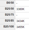
Here's what those numbers mean: at temperatures from 25 °C to 50 °C, the B value is 3380 (K is Kelvins) while at 25 °C to 85 °C, the B value becomes 3434. The B value increases to 3455 at 25 °C to 100 °C.
Knowing the exact temperature range for your application is needed to use the correct B value.
Interface Circuit
Since microcontrollers read voltage and not resistance, we need to find a way to convert the resistance change to voltage change. The simplest circuit to use is a voltage divider:

I recommend using the 3.3V as supply for the circuit because it is less noisy compared to the 5V supply on the Arduino board. For bare microcontrollers like PICs, there is no problem using the 5V supply.
The 10k resistor is chosen because it is the same value as the nominal (R0) value of my thermistor. This makes it more sensitive to resistance changes compared to having a large difference between the two.
Let's say the temperature is 27 °C and the maximum possible temperature is 100 °C. Using the same thermistor as our example above, the B value should be 3380. Manipulating the equation, the resistance at 27 °C is therefore,

In the voltage divider circuit, the corresponding voltage to this resistance would be:
This voltage value would then be interpreted by the analog to digital converter as:
A better equation is to combine the voltage divider equation with the analog-to-digital equation like this,
So here's how the above equations translate to an Arduino sketch:
double codeval;
double therm_res;
long series_res = 10000;

codeval = analogRead(A0);
therm_resistance = (1023 - codeval)/(codeval * series_res);

Serial.print("Thermistor Resistance: ");
Serial.println(therm_resistance);
Once we have the thermistor resistance, all we need is use the Steinhart-Hart equation to find the temperature:
double temp, temp_in_celsius, temp_in_fahrenheit;
temp = 1/(1/298.15 + (1/ 3455)*log(therm_resistance/10000));  //temperature in Kelvin
temp_in_celsius = temp + 273.15; //temperature in Celsius
temp_in_fahrenheit = temp_in_celsius * 1.8 + 32;  //temperature in Fahrenheit
The above code works but there will always be reading errors due to measurement noise and other factors. Thus, it's better to take as many samples as you can and get the average of those samples. Let's say we use 100 samples:
for(int i = 0; i < 100 ; i++){
codeval += analogRead(A0);
}
codeval = codeval/100;
This would be the full code for a thermistor-based arduino temperature sensor:
double codeval;
double therm_res;
long series_res = 10000;
double temp, temp_in_celsius, temp_in_fahrenheit;

void setup() {
// put your setup code here, to run once:
Serial.begin(9600);
pinMode(A0,INPUT);
}

void loop() {
// put your main code here, to run repeatedly:
for(int i = 0; i < 100 ; i++){
codeval += analogRead(A0);
}
codeval = codeval/100;
therm_res = (1023 - codeval)/(codeval * series_res);
temp = 1/(1/298.15 + (1/3455)*log(therm_res/10000));//temperature in Kelvin
temp_in_celsius = temp + 273.15; //temperature in Celsius

Serial.print("Celsius: ");
Serial.println(temp_in_celsius);
Serial.print("Fahrenheit: ");
Serial.println(temp_in_fahrenheit);
}
The sketch above is what I used for my Arduino temperature sensor project. Here it is in action:


shouldn't the equation above be R = codeValue x Rser / (1023 - codeValue)
As you are cross dividing. I am using your analysis for a project but i think the last equation is inverted??
Hi,
the picture shows a nice sensor with handle, where you get this sensor?
Walter