This guide shows how to interface the MH-ET LIVE Scanner V3.0 with Arduino using the UART serial interface. This scanner can read 1D barcodes and 2D codes including QR, and outputs the decoded text through UART or USB.
1. Overview of the Module
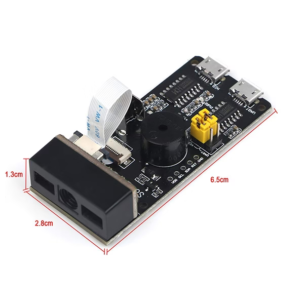
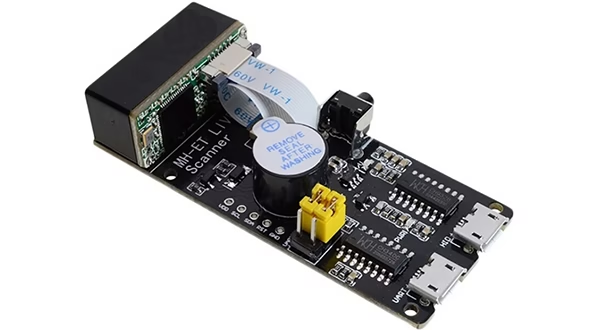
Your MH-ET Scanner board includes:
- 2D scanning engine (CMOS sensor + decoder)
- Two Micro-USB ports
- UART USB → Virtual COM port
- HID USB → Emulates a keyboard
- 6-pin interface block containing:
- UART-TX / UART-RX
- S-TX / S-RX (raw TTL UART, ideal for Arduino)
- HID-TX / HID-RX
- Two jumper headers
- Selects which interface connects to the scanner engine
- RST pin for hardware reset
- VCC / GND for power (5V required)
2. Understanding the 6-Pin Header & Jumper Settings
The key to using this module is understanding how data flows.
6-Pin Header (left → right)
| Pin block | Description |
|---|---|
| UART-TX / UART-RX | Connected to the USB-UART chip (via UART microUSB) |
| S-TX / S-RX | Raw 5V UART pins for microcontrollers |
| HID-TX / HID-RX | Connected to HID-USB chip (keyboard mode) |
Jumper Selection
There are two jumpers:
- UART ←→ S: Connect S-TX/RX to USB-UART chip
- HID ←→ S: Connect S-TX/RX to USB-HID chip
For Arduino, we do not use the jumpers at all — we directly wire to S-TX and S-RX, which always connect to the scanner engine.
3. Power Requirements
The scanner must be powered at 5V, not 3.3V.
At 3.3V, the LED driver and CMOS sensor do not get enough current → QR codes fail to scan.
Recommended:
- 5V / 500mA supply
- Add 100 µF capacitor across VCC–GND if using long wires
4. Wiring the Module to Arduino
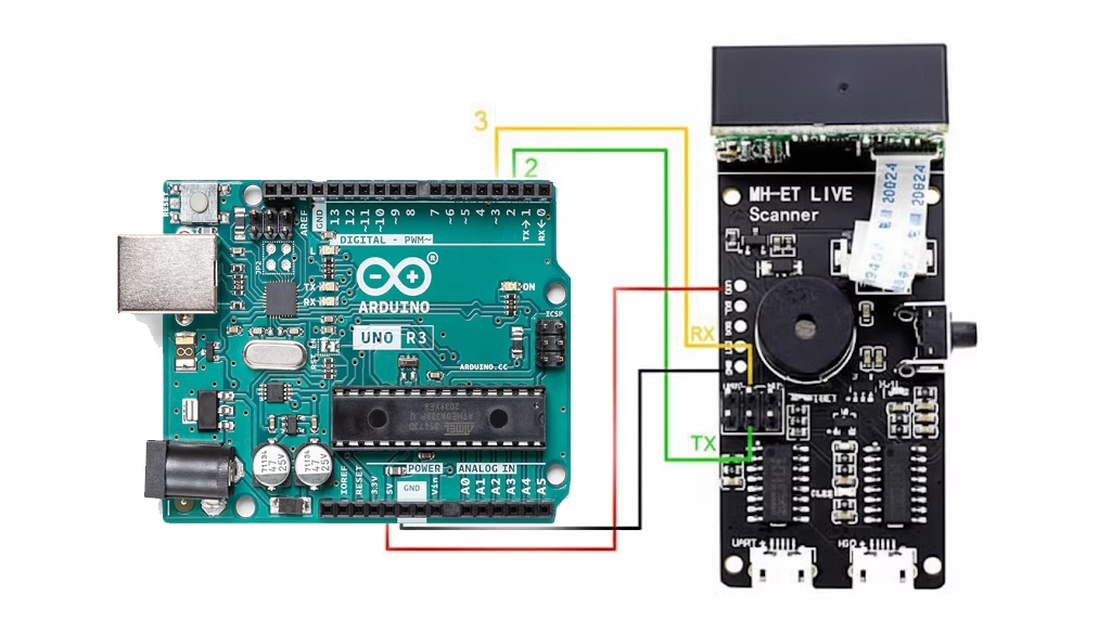
Arduino UNO / Nano WIRING
| Scanner Pin | Arduino Pin |
|---|---|
| S-TX | D2 (Arduino RX using SoftwareSerial) |
| S-RX | D3 (Arduino TX using SoftwareSerial) |
| RST | D4 (not pictured, optional) |
| VCC | 5V |
| GND | GND |
S-TX → Arduino RX
S-RX → Arduino TX
(TX always goes to the other device’s RX)
5. Arduino Code (Tested & Working)
This code:
- Initializes serial communication
- Listens for decoded data
- Resets the scanner if needed
- Prints QR/barcode results to Serial Monitor
6. Confirming Baud Rate
Most units default to 9600, but some ship at 115200.
If you see:
- Random characters
- Half-printed QR values
- Nothing at all
Try:
7. Reset Pin (RST) Details
The scanner’s RST pin is active LOW:
- Pull LOW 10–20 ms → module resets
- Releases HIGH → boots in ~500 ms
This is helpful if:
- Scanner stops responding
- Power dips
- Switching between HID/UART modes
- After scanning configuration QR codes
8. Testing QR & Barcode Scanning
For reliable scanning:
✔️ Use 5V power
3.3V causes QR detection to fail.
✔️ Ideal scan distance
10–20 cm away
(QR is most sensitive to focus distance.)
✔️ Best QR size
25–30 mm square
✔️ Avoid shiny screens and reflections
If scanning fails:
- Increase ambient lighting
- Move slightly farther/closer
- Try a simpler QR (Hello World)
9. Using USB Modes (Optional)
A. USB-UART Mode
Jumper UART ↔ S
Then connect UART microUSB → PC
Open PuTTY / TeraTerm, baud = 9600
B. USB-HID Mode
Jumper HID ↔ S
Then connect HID microUSB
Scanner types text like a keyboard.
10. Troubleshooting
❌ Scanner reads no QR codes
✔ Fix: Use 5V, not 3.3V
✔ Fix: Correct distance (15–20 cm)
❌ Only 1D barcodes read
Scanner may be in 1D-only mode
→ Scan configuration QR to enable 2D.
❌ Arduino receives gibberish
✔ Baud rate mismatch
✔ Long wires → noise
❌ Scanner freezes
✔ Call
scannerReset();11. Bonus: Auto-Recover Watchdog
If scanner becomes idle/unresponsive:
12. Testing Other Modes and Configurations
The MH-ET Live QR code scanner supports a lot of configuration options. You can switch between the options by directly scanning pre-defined QR codes. The configuration QR codes can be viewed in this document.
Finished!
You now have a complete working setup for:
- Reading QR codes
- Reading 1D barcodes
- Hardware reset via RST
- UART communication via S-TX/S-RX
- Arduino-compatible powering
- Full troubleshooting and configuration process


 Tutorial")