
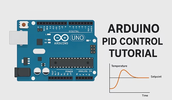
In a feedback control system, a controller continuously adjusts an output so that the measured value moves toward a desired target. One of the most widely used feedback controllers is the PID controller, named after its three control terms: Proportional (P), Integral (I), and Derivative (D).
In this Arduino PID tutorial, we'll look at how PID control works, implement a PID controller manually in Arduino code, use the popular PID_v1 library, and learn how to tune the Kp, Ki, and Kd constants.
Arduino PID Quick Start
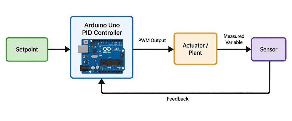
An Arduino PID controller repeatedly performs four basic steps:
- Measure the current value of the system.
- Compare it with the desired setpoint.
- Calculate the error.
- Adjust an actuator based on the PID calculation.
For example, consider an Arduino controlling the speed of a DC motor:
| PID Variable | Motor Speed Example |
|---|---|
| Setpoint | Desired motor speed, such as 1000 RPM |
| Input | Actual RPM measured by an encoder |
| Error | Desired RPM − actual RPM |
| Output | PWM value sent to the motor driver |
| Kp | Correction based on the current error |
| Ki | Correction based on accumulated error |
| Kd | Correction based on how quickly the error is changing |
The basic PID equation is:

where:

Here, r(t) is the setpoint, y(t) is the measured value, e(t) is the error, and u(t) is the controller output.
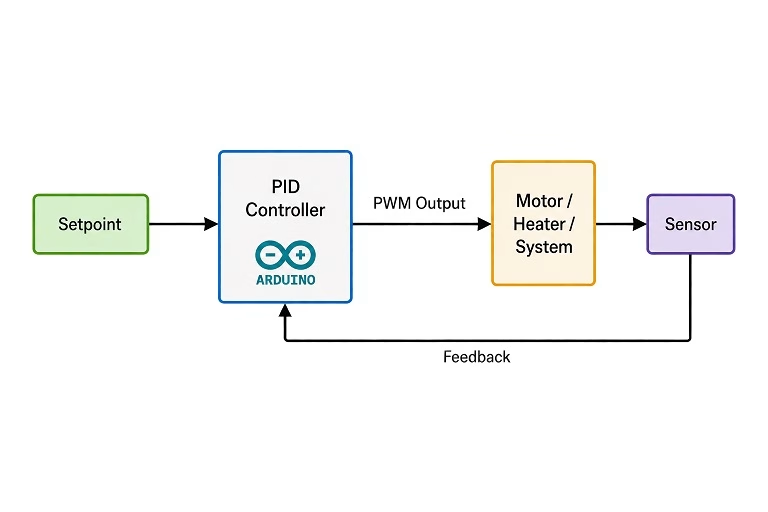
What is PID Control?
PID is short for proportional, integral, and derivative. Each term reacts to the error differently. A PID controller normally operates inside a closed-loop or feedback system. A sensor measures what the system is actually doing and feeds that information back to the controller. For example, imagine a system controlling the temperature inside a furnace:
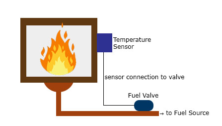
Suppose we want the furnace to remain at 120 °C. This desired temperature is the setpoint. A temperature sensor measures the actual furnace temperature. If the measured value is 110 °C, then the error is:

The PID controller uses this error to determine how strongly the heater, valve, motor, or other actuator should be driven.
Proportional Control
The proportional term produces a correction proportional to the current error. If the error is large, the controller makes a large correction. If the error is small, it makes a smaller correction.
Mathematically:

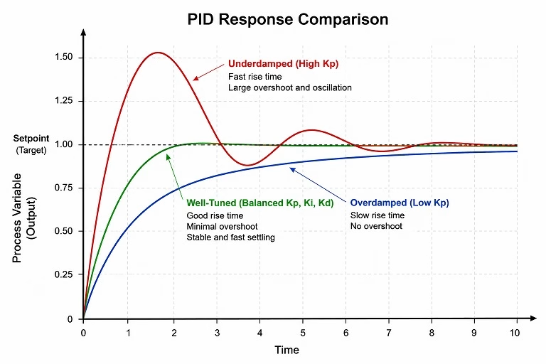
Increasing Kp usually makes the system respond faster. However, too much proportional gain can cause overshoot or continuous oscillation around the setpoint. Proportional control by itself can also leave a small persistent difference between the setpoint and measured value. This is called steady-state error.
Integral Control
The integral term responds to error that has accumulated over time:

Imagine that our furnace continuously settles at 118 °C even though the setpoint is 120 °C. The error is only 2 °C, but because this error remains for a long period, the integral term continues accumulating it. The controller gradually increases its output until the remaining steady-state error is removed. This is the primary job of the integral term: eliminating persistent error that proportional control alone cannot remove. However, too much integral action can cause overshoot and a problem called integral windup, which we'll discuss later.
Derivative Control
The derivative term reacts to how quickly the error is changing:

Suppose the furnace temperature is rising rapidly toward its setpoint. Even if the current error is still fairly large, the derivative term sees that the temperature is approaching the target quickly. The derivative term can therefore reduce the controller output before the system overshoots. You can think of derivative action as adding damping to the system.
Derivative control can reduce overshoot and oscillation, but it has one major disadvantage: sensor noise can appear as rapid changes in the measured signal. Because derivative control reacts to rapid changes, too much Kd can make the controller output noisy or unstable.
A complete feedback system with a PID controller looks like this:
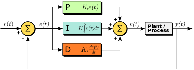
Here:
- r(t) is the desired value or setpoint.
- y(t) is the measured output.
- e(t) is the difference between the setpoint and measured output.
- u(t) is the control signal sent to the plant or actuator.
A PID controller is not normally useful with arbitrary Kp, Ki, and Kd values. These constants must be tuned according to the actual behavior of the system.
PID Term Effects Overview
The table below summarizes the typical effect of each PID term.
| PID Term | Main Effect | Increasing It Usually... | Too Much Can Cause |
|---|---|---|---|
| Kp | Reacts to present error | Speeds up response and reduces error | Overshoot and oscillation |
| Ki | Reacts to accumulated error | Removes steady-state error | Overshoot and integral windup |
| Kd | Reacts to rate of change | Adds damping and reduces overshoot | Noise sensitivity and jitter |
Keep in mind that these effects depend heavily on the physical system being controlled. A set of PID values that works well for a slow heater may be completely unsuitable for a fast DC motor.
Implementing PID in Arduino Code
Before using a PID library, it is useful to understand how the calculation can be implemented manually.
We need the following values:
| Parameter | Description |
|---|---|
| Kp | Proportional gain |
| Ki | Integral gain |
| Kd | Derivative gain |
| input | Current measured value |
| setPoint | Desired target value |
| dt | Time since the previous PID calculation |
Step 1: Measure the Elapsed Time
The integral and derivative terms both depend on time.
Arduino's millis() function returns elapsed time in milliseconds, but it is generally easier to perform PID calculations using seconds.
currentTime = millis();
dt = (currentTime - previousTime) / 1000.0;
Dividing by 1000 converts milliseconds to seconds.
Step 2: Calculate the Error
The error is the difference between the setpoint and the measured input:
error = setPoint - input;If the setpoint is 600 and the current input is 550:
error = 600 - 550; // error = 50Step 3: Calculate the Integral Term
The integral accumulates error over time:
integral += error * dt;One problem is that this value can continue growing while the actuator is already at its maximum output. This is called integral windup. A simple way to reduce this problem is to limit the accumulator:
integral += error * dt;
integral = constrain(integral, -integralLimit, integralLimit);
Step 4: Calculate the Derivative Term
The derivative measures how quickly the error has changed:
derivative = (error - previousError) / dt;A rapidly changing error produces a larger derivative term.
Step 5: Calculate the PID Output
The three terms are multiplied by their respective gains and added together:
output = Kp * error
       + Ki * integral
       + Kd * derivative;
For an Arduino Uno PWM output, the final result might be limited to the range 0 to 255:
output = constrain(output, 0, 255);Notice that limiting the final output and limiting the integral accumulator are two different things. Simply applying constrain() to the final output does not by itself prevent integral windup.
Full Manual Arduino PID Example
The following example demonstrates the PID calculation using an analog input and a PWM output. This is intended to demonstrate the PID algorithm itself. In a real project, the analog input would normally come from a sensor measuring a physical process such as temperature, position, pressure, or speed.
// PID constants - these must be tuned for your system
double Kp = 2.0;
double Ki = 0.5;
double Kd = 0.1;

// PID variables
double setPoint = 600.0;
double previousError = 0.0;
double integral = 0.0;

const double integralLimit = 500.0;

unsigned long previousTime;

const int inputPin = A0;
const int outputPin = 3;

void setup() {
  pinMode(outputPin, OUTPUT);
  Serial.begin(115200);

  previousTime = millis();
}

void loop() {
  double input = analogRead(inputPin);
  double output = computePID(input);

  analogWrite(outputPin, (int)output);

  Serial.print("Input: ");
  Serial.print(input);

  Serial.print("\tError: ");
  Serial.print(setPoint - input);

  Serial.print("\tOutput: ");
  Serial.println(output);

  delay(10);
}

double computePID(double input) {
  unsigned long currentTime = millis();

  double dt = (currentTime - previousTime) / 1000.0;

  // Avoid division by zero if computePID() is called
  // more than once within the same millisecond.
  if (dt <= 0.0) {
    return 0.0;
  }

  double error = setPoint - input;

  // Integral
  integral += error * dt;

  // Simple anti-windup limit
  integral = constrain(integral,
                       -integralLimit,
                        integralLimit);

  // Derivative
  double derivative =
      (error - previousError) / dt;

  // PID equation
  double output =
      Kp * error +
      Ki * integral +
      Kd * derivative;

  // Arduino Uno PWM range
  output = constrain(output, 0.0, 255.0);

  previousError = error;
  previousTime = currentTime;

  return output;
}
This example uses a unidirectional 0–255 output. If you are controlling a bidirectional DC motor, your PID output can instead represent positive and negative torque or speed. An H-bridge would then determine motor direction while the magnitude controls PWM.
For example:
output = constrain(output, -255.0, 255.0);

if (output >= 0) {
  // Forward
  setMotorDirectionForward();
  analogWrite(pwmPin, output);
} else {
  // Reverse
  setMotorDirectionReverse();
  analogWrite(pwmPin, -output);
}
The actual motor-driver code will depend on the H-bridge you are using.
Using the Arduino PID Library
Writing the PID calculation manually is useful when learning how the controller works. For actual Arduino projects, however, it is often more convenient to use the PID_v1 library originally written by Brett Beauregard.
The library handles important details such as:
- PID calculation timing
- Output limits
- Integral limiting
- Controller direction
- Changing Kp, Ki, and Kd while the program is running
Installing PID_v1
In the Arduino IDE:
- Go to Sketch → Include Library → Manage Libraries...
- Search for PID.
- Install PID by Brett Beauregard.
- Include the library in your sketch:
#include <PID_v1.h>Basic Arduino PID_v1 Example
The basic structure is:
#include <PID_v1.h>

#define PIN_INPUT  A0
#define PIN_OUTPUT 3

double Setpoint;
double Input;
double Output;

double Kp = 2;
double Ki = 5;
double Kd = 1;

PID myPID(&Input,
          &Output,
          &Setpoint,
          Kp,
          Ki,
          Kd,
          DIRECT);

void setup() {
  Serial.begin(115200);

  Setpoint = 100;

  Input = analogRead(PIN_INPUT);

  myPID.SetOutputLimits(0, 255);
  myPID.SetMode(AUTOMATIC);
}

void loop() {
  Input = analogRead(PIN_INPUT);

  if (myPID.Compute()) {
    analogWrite(PIN_OUTPUT, (int)Output);
  }

  Serial.print("Input: ");
  Serial.print(Input);

  Serial.print("\tOutput: ");
  Serial.println(Output);
}
Four variables are especially important:
- Input — the measured process variable
- Setpoint — the desired value
- Output — the resulting control signal
- Kp, Ki and Kd — the tuning constants
The PID object connects these variables:
PID myPID(&Input,
          &Output,
          &Setpoint,
          Kp,
          Ki,
          Kd,
          DIRECT);
The library then periodically calculates the required output when myPID.Compute() is called.
Important PID_v1 Functions
| Function | Purpose | Example |
|---|---|---|
| Compute() | Runs a PID calculation when the sample period has elapsed | myPID.Compute(); |
| SetMode() | Switches between automatic and manual modes | myPID.SetMode(AUTOMATIC); |
| SetTunings() | Changes Kp, Ki, and Kd | myPID.SetTunings(2.5, 0.4, 0.8); |
| SetSampleTime() | Changes the PID calculation interval | myPID.SetSampleTime(50); |
| SetOutputLimits() | Limits the controller's output range | myPID.SetOutputLimits(0, 255); |
| SetControllerDirection() | Changes between DIRECT and REVERSE operation | myPID.SetControllerDirection(REVERSE); |
DIRECT vs REVERSE PID Control
Choosing the correct controller direction is important. Use DIRECT when increasing the controller output causes the measured input to increase.
For example:
More PWM → faster motoror:
More heater power → higher temperatureUse REVERSE when increasing the output causes the measured input to decrease. If your Arduino PID controller appears to drive the system away from the setpoint, checking the controller direction should be one of your first troubleshooting steps.
Manual PID vs PID_v1
| Aspect | Manual PID | PID_v1 |
|---|---|---|
| Timing | You calculate dt yourself | Handled internally |
| Integral limiting | You implement it | Handled with output limits |
| Output limits | Manual | SetOutputLimits() |
| Direction | You handle the sign | DIRECT / REVERSE |
| Gain changes | Manual variables | SetTunings() |
| Best suited for | Learning or specialized controllers | Most normal Arduino PID projects |
Try the Arduino PID Tuning Calculator
Calculate starting Kp, Ki, and Kd values using common PID tuning methods, then copy the generated Arduino PID_v1 code.
How to Tune an Arduino PID Controller
Finding suitable Kp, Ki, and Kd values is called PID tuning.
There is no universal set of PID values. The correct constants depend on factors such as:
- Motor inertia
- Sensor response time
- Heating or cooling rate
- Mechanical load
- Sampling interval
- Actuator limits
A good manual starting procedure is:
1. Start With Kp Only
Set:
Ki = 0;
Kd = 0;
Increase Kp gradually. You want the system to respond quickly enough to errors without entering continuous oscillation. Do not automatically assume that you must increase Kp until the system becomes unstable. Some formal tuning methods deliberately create oscillation, but this is not appropriate for every motor, heater, robot, or mechanical system.
2. Add Ki
If the system gets close to the setpoint but consistently stops slightly above or below it, increase Ki gradually. Integral action removes this steady-state error.
Too much Ki typically causes:
- Large overshoot
- Slow oscillations
- Integral windup
- Long recovery after actuator saturation
3. Add Kd If Necessary
Kd can help reduce overshoot and damp oscillation. Increase it cautiously because derivative control is sensitive to sensor noise. Some systems require very little derivative gain. Others work perfectly well as PI controllers with Kd set to zero.
PID Tuning Troubleshooting Table
| Observed Behavior | Possible Adjustment |
|---|---|
| Response is very slow | Increase Kp gradually |
| System never quite reaches the setpoint | Increase Ki slightly |
| Large overshoot | Reduce Kp or Ki; consider adding Kd |
| Continuous rapid oscillation | Reduce Kp |
| Slow repeated oscillation | Reduce Ki |
| Output is noisy or jittery | Reduce Kd or filter the sensor input |
| Output stays at maximum for a long time | Check for integral windup |
| System moves away from setpoint | Check error sign and DIRECT/REVERSE direction |
Arduino PID Example: Line Follower Robot
A line follower robot is a good practical example of PID control because the Arduino must continuously correct the robot's position relative to a line. Instead of controlling temperature or motor RPM directly, the process variable is the robot's position over the line. The basic calculation looks like this:
error = position - setpoint;

P = error;
I += error;
D = error - previousError;

correction =
    Kp * P +
    Ki * I +
    Kd * D;

leftMotorSpeed  = baseSpeed + correction;
rightMotorSpeed = baseSpeed - correction;

previousError = error;
If the robot moves too far toward one side of the line, the PID correction increases one motor speed while reducing the other. The proportional term reacts to the current position error, the integral term reacts to persistent bias, and the derivative term reacts to how quickly the robot is moving away from or toward the line. I have a separate project showing the complete implementation here:
Implementing PID for a Line Follower Robot
This is also a useful example of why PID constants cannot simply be copied from another project. The correct values depend on motor speed, wheel traction, sensor placement, robot weight, and many other physical factors.

PID Tuning Example: Temperature Control
Temperature control is another classic application of Arduino PID. Consider a system consisting of:
- Arduino Uno or compatible board
- LM35 or TMP36 temperature sensor
- Logic-level MOSFET
- Low-voltage heating element
- External power supply suitable for the heater
The objective might be to maintain a temperature of:
Setpoint = 40 °CThe Arduino measures the temperature and changes the heater power according to the PID output.
For this type of system:
Input    = measured temperature
Setpoint = desired temperature
Output   = heater PWM or power command
Example Tuning Process
Start with proportional control:
Kp = initial value
Ki = 0
Kd = 0
Increase Kp until the heater responds adequately without producing excessive overshoot. Then introduce a small Ki value to remove any persistent error between the actual temperature and the setpoint. Finally, if necessary, introduce Kd to add damping. The following values are only an example:
| Parameter | Example Value |
|---|---|
| Kp | 2.0 |
| Ki | 0.5 |
| Kd | 1.0 |
| Setpoint | 40 °C |
These are not universal tuning values. Actual PID gains must be determined from the physical system.
Observing the PID Response
The graph below illustrates the type of response you may observe while tuning a PID temperature controller:
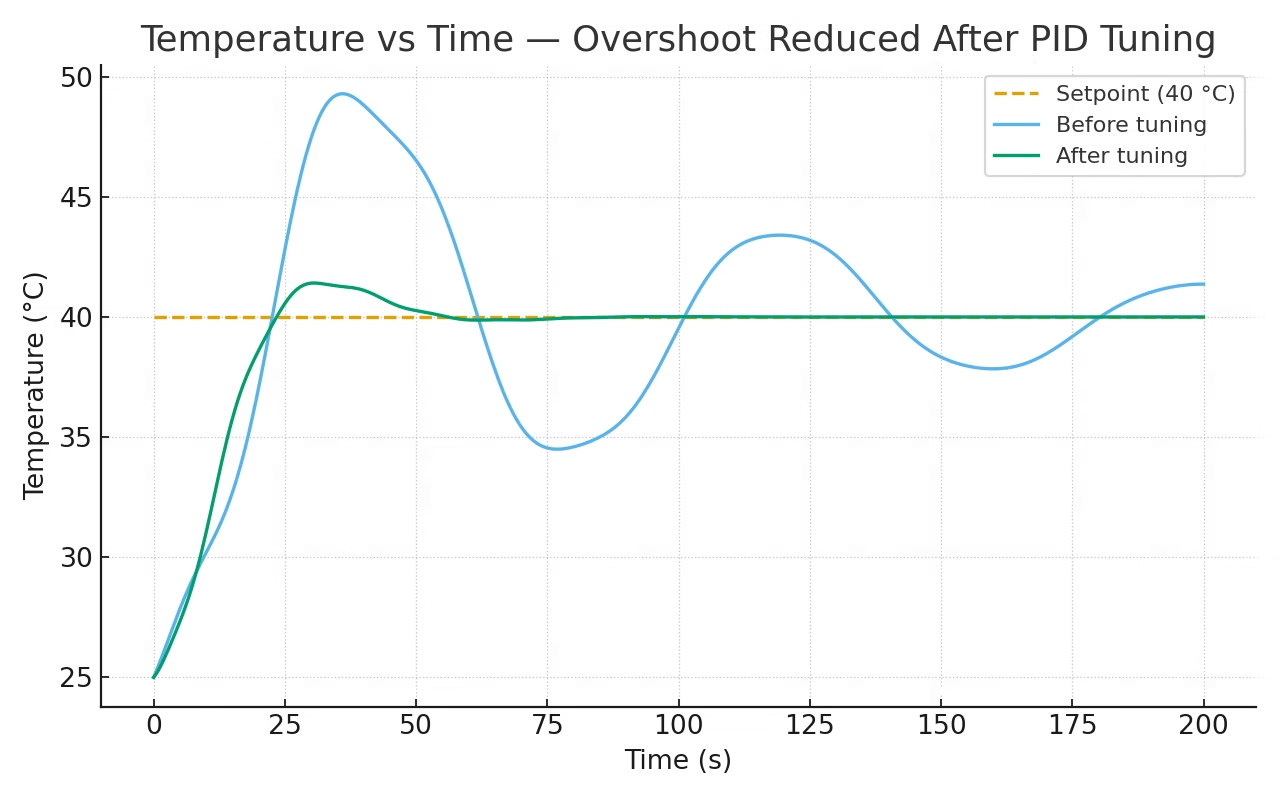
In general:
- Increasing Kp can reduce rise time.
- Ki can remove persistent steady-state error.
- Kd can reduce overshoot and add damping.
To observe your own controller, print the setpoint, measured input, and output:
Serial.print("Setpoint:");
Serial.print(Setpoint);

Serial.print(",Input:");
Serial.print(Input);

Serial.print(",Output:");
Serial.println(Output);
You can then use the Arduino IDE's Serial Plotter to see how the measured value approaches the setpoint. A real measured response plot would be especially valuable here because it lets you compare the effect of changing Kp, Ki, and Kd on actual hardware.
Choosing the PID Sample Time
The PID controller should not run arbitrarily fast or slow. If the sample time is much slower than the dynamics of the system, the controller may react too late. If the PID loop is much faster than necessary, noise and derivative calculations may become more significant without improving the system.
As a general starting point:
| Application | Possible Starting Sample Time |
|---|---|
| Slow temperature system | 500–2000 ms |
| General motor speed control | 20–100 ms |
| Fast position or robotics loop | Often below 20 ms, depending on hardware |
These values are only starting points. The sample time should be significantly shorter than the time scale of the physical response you are trying to control.
With PID_v1:
myPID.SetSampleTime(50);sets a 50 ms PID calculation period.
Understanding Integral Windup
Integral windup occurs when the integral term keeps accumulating error even though the actuator has already reached its physical limit. Suppose your Arduino PID output is limited to 0 to 255, but the controller continues demanding more power because the system has not yet reached its setpoint. The real PWM output cannot exceed 255, but the integral value may continue increasing internally.
When the system finally approaches the setpoint, the accumulated integral term can remain very large. The controller may therefore continue driving the actuator even though the error has already become small. The result is usually severe overshoot and slow recovery.
In a manual PID implementation, one simple anti-windup technique is:
integral += error * dt;

integral = constrain(integral,
                     -integralLimit,
                      integralLimit);
With PID_v1, set an output range appropriate for your actuator:
myPID.SetOutputLimits(0, 255);For a heater or one-direction motor drive, 0–255 may be appropriate. For a bidirectional controller, another range may make more sense.
Arduino PID Troubleshooting and FAQs
Why does my PID output oscillate rapidly?
Kp may be too high, Kd may be reacting to noisy measurements, or your sampling interval may be inappropriate. Start by reducing Kp. If the measured input is noisy, inspect or filter the sensor signal before increasing derivative gain.
Why does the system stop before reaching the setpoint?
This is usually called steady-state error. Increase Ki gradually so that persistent error accumulates and produces additional correction. Also verify that the actuator is physically capable of reaching the requested setpoint.
Why does my PID controller overshoot badly?
Possible causes include:
- Kp is too high.
- Ki is too high.
- Integral windup is occurring.
- The actuator or plant has significant delay.
Reduce the gains gradually and make sure the integral term is properly limited.
Why does Kd make the output noisy?
The derivative term responds to rapid signal changes. Noise from an ADC, encoder, or sensor can therefore look like a rapidly changing process variable.
Possible solutions include:
- Reducing Kd
- Improving sensor wiring
- Filtering the input signal
- Using a more appropriate sample time
Avoid simply adding large blocking delays to hide the problem because this also changes the timing of the controller.
Why does my Arduino PID run in the wrong direction?
Check the sign of your error:
error = setPoint - input;Also check whether your system requires:
DIRECTor:
REVERSEwhen using PID_v1.
Can I use PID_v1 on ESP32?
Yes, PID control can also be implemented on the ESP32 using the Arduino framework. However, remember that PWM configuration and resolution differ from the classic Arduino Uno. Your PID output limits should match the way your ESP32 PWM output is configured.
Can I use PID on STM32?
Yes. PID itself is simply a control algorithm and can be implemented on virtually any microcontroller. If you are using an Arduino-compatible STM32 core, an Arduino PID library may also work depending on the core and library version. Otherwise, the manual PID equations shown earlier can easily be implemented in normal STM32 C or C++ code.
Do I always need Kp, Ki, and Kd?
No. Many real systems use:
- P control
- PI control
- PD control
- PID control
For example, a system that does not suffer from significant steady-state error may not need integral action. Likewise, a noisy system may work better without derivative action. PID should be treated as a set of tools rather than a requirement that all three terms must always be used.
Arduino PID Summary
An Arduino PID controller continuously compares a measured input with a desired setpoint and calculates an output from three terms:
- Kp reacts to the current error.
- Ki reacts to accumulated error and removes steady-state error.
- Kd reacts to how quickly the error is changing and can reduce overshoot.
When tuning an Arduino PID controller:
- Start with Ki and Kd at zero.
- Increase Kp until the system has a useful response without excessive oscillation.
- Add Ki gradually if steady-state error remains.
- Add Kd only when additional damping is useful.
- Set realistic output limits.
- Watch for integral windup.
- Use a sample time appropriate for the physical system.
- Plot the actual response whenever possible instead of tuning only by feel.
For most Arduino projects, the PID_v1 library provides a convenient implementation. However, understanding the underlying calculation makes it much easier to diagnose oscillation, overshoot, steady-state error, and other problems when your controller does not behave as expected.
For a complete Arduino project using PID control, see my PID line follower robot tutorial.
If you have questions about implementing or tuning Arduino PID control components for your project, feel free to leave a comment below.
for the code you provided and not the library , where do i write the value of my setpoint?
How to implement PID temperature control for MLX90614 IR sensor which gives reading I2C.
Hi,
Get the temperature data and make it an input to the PID. The output of the PID is then used to control whatever that is generating heat on your project
I WANT TO CONNECT A FAN IN CASE MY TEMP IS LESSER THAN THE SET POINT.WHAT CHANGING I SHOULD DO
Hi, I'm trying to balance a robot with one wheel using a stepper motor and accelerometer data that gives me current angle ... How can I implement the PID controller?
Hello,
The basic idea would be that the input to your PID is the current angle of the robot while the output is the number of steps the stepper motor needs to move to counteract the offset of the robot. I’ve actually done a self balancing robot before but it was done using dc motors so I cant give anything more specific for your case.
hello can i get the code for the self balancing robot? my robot would not give a feedback when it is turned on.
In your PID implementation (not the library) you use lastError before assignment, you should probably assign it a default value in setup just to be safe.
Hi,
My project is to control an actual which elongates by inflating or deflating air into. An amount of air is controlled by a velocity of air_pump. A distance is measured by a proximity sensor. So how can I use a PID algorithm to control the velocity of the air-pump, which is used to manipulate the actuator to a setpoint, based on a feedback value from the proximity sensor?
I have no idea about PID things. can you explain how could you get the value of KP, KI, and KD
Hi, nice explanation, thanks for that. I'm dealing with the following: in order to fire up (bake) ceramics, i need to gradually increase the temperature (let's say, going up to 650°C in about 6 hours). I like to use PID control to keep the temperature as close to the desired temperature as possible (on that point in time) but since i have to change (increase) the temperature gradually, the "set point" will keep changing over time. Do you think this would be possible? Raising the "set point" would result in an detected error thus "confusing" the derivative control, right? Or am i overthinking this a bit? 🙂 Thanks again. Cheers. p
Hi,
That’s a good question. Actually, PID controller works with variable set points, as long as the variation is not random. Your example of gradually changing the set point temperature is a ramp type input, a common type of input in control systems. In your case, the error continuously changes because of the variation for both set point and actual temperature. The derivative term will deal with how fast that error is changing so there’s no problem there.
Thank you for your answer, Roland! I'll give it a shot.
Hi,
I am trying to build a differential drive robot(DDR) with DC motors with Arduino. The problem is that the built DDR does not move in a straight line because the two motors run at different speeds for the same input given by Pulse width Modulation.
Now, I had a plan to implement the PID controller in Arduino to control the DC motor. or to use a stepper motor or to use a Servo motor. Kindly give your opinion regarding this.
Thank you
How to determine the values of Kd, Kp, Ki??
Hello,
Thanks for the code. On this line:
analogWrite(3, output); //control the motor based on PID value
What is the 3 for?. Does it mean Pin 3?. Would it not have to be also defined as A3 or B1 or C0...etc??
On the other hand a ";" is missing after every PID constant at the beginning. "setpoint" is written with different capital letters. Just thought I would mention it for those who struggle because of those details detail.
https://playground.arduino.cc/Code/PIDAutotuneLibrary/
Hi,
To calculate the integral and derivative error, shouldn't we use the elapsed time in seconds instead of milliseconds?
I mean, dividing elapsedTime by 1000?
Is it possible to do multiple PID loop in single arduino code?
Very clear explanations.
This article is the best I have found on the Internet today.
Thanks a lot for the time you spend on this for us 😉
can you help me how to make coding to robot path tracer?i'm a newer for robotics project in my school
hi, assuming I have a 0 knowledge in PID, but were tasked to make a color sorter using PID in arduino, how do i code it and what are the tips or information i need to know? thankyou
hi, im trying to use PID library for a DC/DC boost converter but i kind confuse how to implement it.
when the dc motor reaches the specified set point the motor must stop. ie: the output must become zero, but if we use integral , when the error becomes zero, the cumulative error is still non zero thus making the output non zero hence the motor would still continue to run even after the set point is achieved. Correct me if I am wrong.
please how can implement PID controller with DHT sensor and dc fan motor
Hi,
I assume that your input is temperature and output is the current to the fan. You need to establish a numerical relationship between the temperature and how much current is needed to drive the fan.
Hi there, I have been trying to implement PID for regulating a PDLC film on the basis of temperature, I am using an ESP32 instead of an arduino. I am facing some problems with how to implement the same. Would be happy for your input
Hi,
I saw lot of videos about self balancing robots and I would like to build one. For this purpose I would use MPU-6050 and 2 DC motor with L298N motor driver and one Arduino Nano. I study vehicle engineering so I may say it is a little familier to me 😀 but also I could understand far better the concept if I could implement the PID algorithm. I know it would be easier to copy one of the solutions on the net but I want to do it for myself.
In previous comments I read You also bulit slef balancing robot. I would highly appreciate if You could help me and share some information and knowledge with me of your project. How you did it and what helped you to understand this?
Thanks in advance:)
Archi
Hi,
This might be too late of a reply, but you can check the source code for my self-balancing robot here: https://github.com/kurimawxx00/arduino-self-balancing-robot
Pictures of the setup is here: https://hackaday.io/project/21920-ambot
Haha - bunch of folks who want you to write their code for them.
Thanks for the simple explanation.
Im trying to control an rlc circuit system with aurdino as an pid controller. I would like to know if I can give the variable set point to aurdino and how the output of aurdino be connected to be as in input to rlc circuit
Also can the aurdino be configured in discrete controller
Please send me the circuit diagram/schematic of temperature furnace.
the links have been Hacked and don't link to the expected material.
"list of function" and "limitations of PID"