
An Arduino magnetic sensor has several uses: for reading the speed of a rotating object, for door alarms and for navigation. In this tutorial, we will build a simple magnet detector using a hall effect sensor.
Video Tutorial
What is Hall Effect?
Hall effect describes a phenomenon where a voltage builds across a current-carrying conductor due to a presence of a magnetic field.
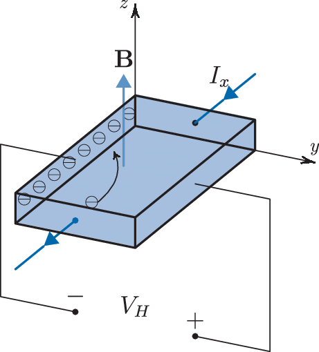
In the illustration shown, an upwards magnetic field is applied to a conductor with flowing electrons (for simplicity, other types of charges may exist). This field introduces a force to the electrons that tends to pull them to the left. This makes the left part of the conductor more negative compared to the right, thus voltage is produced.
Hall Effect Sensor
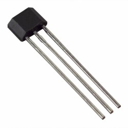
There are manufactured integrated circuits that follow the hall effect principle. These sensors, which looks like transistors, produce an output voltage when a magnet is near them.
Its three pins are VCC, OUT and GND. The nature of what comes out from the OUT pin depends on the type of hall effect sensor: analog or digital.
Analog-type hall effect sensors produce a voltage which varies linearly with the strength of a magnetic field. Meanwhile, digital hall effect sensors contain a Schmitt trigger which produces a logic high voltage in the presence of a magnetic field and zero when there is none. Hall effect “switches” are typically digital types.
Correct polarity is always followed; the front face of the sensor detects the south pole of magnet. Conversely, the back face of the sensor detects the north pole of the magnet.
Hall effect sensors also have different configurations in how they detect magnets. Head-on magnetic sensors detect when the south pole of the magnet moves towards the front face of the sensor. Alternatively, sideways magnetic sensors detect when the south pole of the magnet moves across the front face of the sensor.
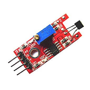
Sensor Module for Arduino Magnetic Sensor
Modules make interfacing sensors to microcontrollers easier. For this tutorial, I am using this hall effect sensor module:

This sensor features the SS49E linear hall effect sensor with a LM393 op-amp IC used as a comparator for digital output. The module also includes a potentiometer for tuning the sensitivity of the digital output.
As seen, there are four output pins where G is ground, + is for a 5V supply, D0 is digital output and A0 is analog output. A red LED turns on when the module is powered. A green LED lights up when the D0 pin goes high. Moreover, the A0 pin connects directly to the OUT pin of the SS49E sensor.
Since the SS49E is a linear type, we can detect not only the presence of the magnet but also its strength. Its datasheet shows this:

The graph shows that the sensor produces a voltage of 1 to 4 V corresponding to a magnetic field intensity of -100 to 100 milliTesla.
Testing the Sensor
As mentioned, the hall effect module provides both analog and digital outputs. If a magnet is detected, the digital output pin goes high and the green LED on the board lights up.
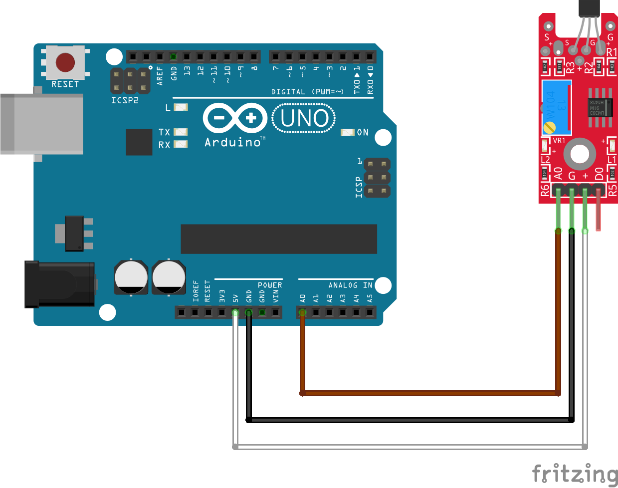
But before that, I wanted to test if the hall effect sensor really can measure magnetic field strength. Thus, I wired the A0 pin of the module to the A0 pin of the arduino:
Then I uploaded the built-in AnalogReadSerial sketch to the Arduino:
// the setup routine runs once when you press reset:
void setup() {
  // initialize serial communication at 9600 bits per second:
  Serial.begin(9600);
}

// the loop routine runs over and over again forever:
void loop() {
  // read the input on analog pin 0:
  int sensorValue = analogRead(A0);
  // print out the value you read:
  Serial.println(sensorValue);
  delay(1);        // delay in between reads for stability
}
Here’s what the serial monitor shows when there is no magnet present:
This value corresponds to a voltage of around 2.6 volts. Now if we look at the graph again:
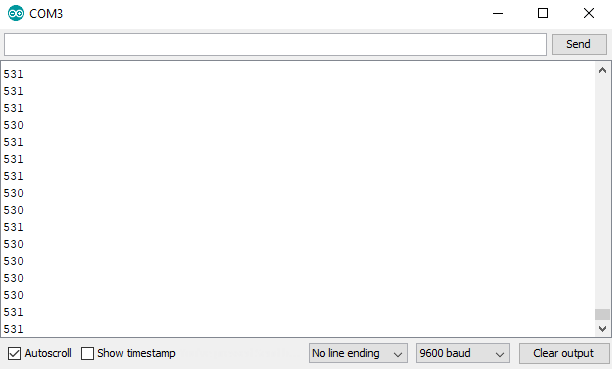

A voltage of 2.5-2.6 means around zero Teslas! With this, I created this formula:
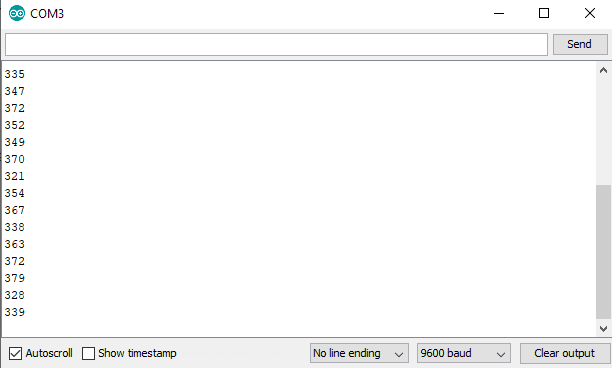
What’s interesting, however, is the value on the serial monitor decreases when a magnet is introduced and the green LED turns on:
Then, I decided to use the other pole of the magnet and the value goes up:
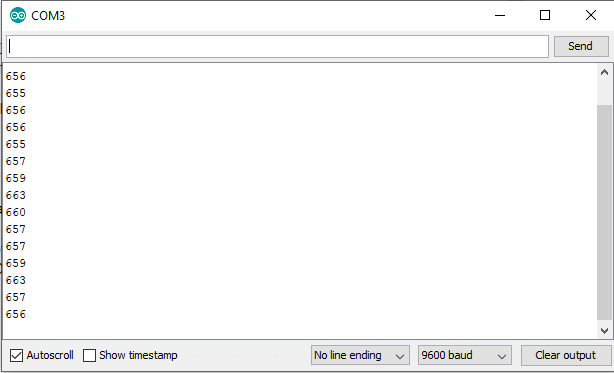
Interestingly, the LED did not turn on this time. This means the LED turns on only when a magnet in one polarity is detected. Similarly, the module gives increasing or decreasing voltage depending on the polarity of the magnet.
Building a Usable Arduino Magnetic Sensor
Now that I know that the hall effect module works, it’s time to build my actual project. I added an LCD and a speaker to the previous Fritzing diagram:

Here’s now the full sketch:
#include <Wire.h>
#include <LiquidCrystal_I2C.h>

int spkr = 7;
int hall_digital = 2;
float value;

LiquidCrystal_I2C lcd(0x27,16,2);  // set the LCD address to 0x27 for a 16 chars and 2 line display

void setup()
{
  lcd.init();                      // initialize the lcd
  lcd.backlight();
  lcd.setCursor(0,0);
  attachInterrupt(digitalPinToInterrupt(hall_digital),magnetDetected,HIGH);
  pinMode(spkr,OUTPUT);
}


void loop()
{
  digitalWrite(spkr,LOW);
  value = analogRead(A0)*5;
  value = value / 1023.0;
  float uTesla = (value - 2.6) * 15;
  float mTesla = (value - 2.6) * 1.5;
  mTesla = mTesla / 100;
  lcd.setCursor(0,0);
  lcd.print(mTesla);
  lcd.print(" ");
  lcd.print("mT ");
  lcd.setCursor(0,1);
  lcd.print(uTesla);
  lcd.print(" ");
  lcd.print("uT ");
  delay(500);
}

void magnetDetected(){
  digitalWrite(spkr,HIGH);
}
You might need the LiquidCrystal I2C library for this sketch to run.
Here, the D0 pin of the module connects to digital pin 2 of the Arduino. Recall that an interrupt can be attached to this pin. So when the D0 pin goes high, the Arduino can react immediately. The interrupt service routine (named magnetDetected here) is just for turning on the speaker.
As before, the A0 pin of the module connects to the A0 pin of the Arduino. For a 10-bit ADC, analogRead returns a value as:
![]()
I reversed this formula in the sketch to get the actual voltage from the module (A0volts). This value is then used as Voutput in the formula I first presented above:
In the video, you will see the how different magnet types give different tesla values.
I hope you find this article on Arduino magnetic sensor useful. Feel free to drop comments, suggestions and reactions in the comments section below!


