
The Internet of Things (IoT) revolution has inspired thousands of makers to build interconnected systems that span the globe. Want to join the revolution? Learn first how to make a PIC16F877 Internet connection! This tutorial will cover using the PIC with the ESP8266 Wi-Fi module both in sending and receiving data to a web server.
Introduction to the ESP8266
The ESP8266 WiFi Module is a chip that comes with a TCP/IP stack and the ability to connect to a WiFi network. The best thing about this module is you can communicate with it serially, which means any microcontroller can use it to connect to the Internet via WiFi. The module has its own memory: 64 KB for instructions and 96 KB for data. The memory allows you to load application directly to the ESP8266 without a microcontroller! In fact, a number of software development kits (SDK) have been created for the ESP8266. I will be creating a more in-depth tutorial about this nifty little WiFi module so make sure to check it out.
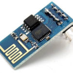
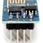
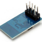
There are quite a number of ESP8266 modules available, 21 modules to be exact (as of this writing). This tutorial will be using the ESP-01 module which looks like this:
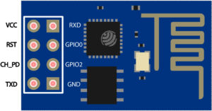
The ESP-01 module pinout:
Each ESP8266 module comes pre-programmed with an AT command set firmware. This allows you to "command" the module serially just like a GSM or a Bluetooth module. Here's a website that lists the whole AT command set for the ESP8266.
For our purpose, I will be using only the AT commands needed to send/receive data to/from the Internet via a WiFi network.
ESP8266 Internet Connection AT Commands
List available Wi-Fi routers:
AT+CWLAP
Reply: +CWLAP: <ecn>, <ssid>, <rssi>, <mac>
ecn: 0 - open 1 - WEP 2 - WPA_PSK 3 - WPA2_PSK 4 - WPA_WPA2_PSK
ssid: SSID of access point
rssi: signal strength
mac: MAC address
WiFi Mode:
AT+CWMODE = <mode>
Mode: 1 - station mode (client) 2 - access point mode (host) 3 - access point + station mode (dual)
Connect to Wi-Fi router:
AT+CWJAP=”<ssid>”,”<password>”
Enable multiple of single connections:
AT+CIPMUX=<mode>
Mode: 0 - single connection 1 - multiple connection
Establish TCP Connection:
AT+CIPSTART=<id>,<type> ,<addr>,<port>
Note: id is omitted for single connections
id - 0-4, id of connection
type - String, “TCP” or “UDP”
addr - String, remote IP
port - String, remote port
Send Data:
AT+CIPSEND=<id>,<length>
Note: id is omitted for single connections
id - 0-4, id of connection length - data length, Max. 2048 bytes
So for example, you want to fetch the home page of this site, you will need to send these commands to the ESP8266 via the serial port:
AT+CIPMUX=1
AT+CWMODE=3
AT+CWJAP="cetfaculty","123456"
AT+CIPSTART=0,"TCP","www.teachmemicro.com","80”
AT+CIPSEND=0,16
GET / HTTP/1.1
The server's reply would be a HTTP header that looks like this:
HTTP/1.1 200 OK
Date: Wed, 15 Mar 2017 22:41:08 GMT
Server: Apache/2.4.25
X-Powered-By: PHP/5.6.30
Vary: Cookie,Accept-Encoding,User-Agent
Link: <https://www.teachmemicro.com/wp-json/>; rel="https://api.w.org/", <http://wp.me/8mj4y>; rel=shortlink
Content-Type: text/html;charset=UTF-8
Transfer-Encoding: chunked
Followed by the HTML of the homepage.
Establishing the PIC16F877 Internet Connection
Before you can send or receive data from the web server, the ESP8266 module must be connected to the Internet first. You should have WiFi already running to proceed.
Connect your ESP8266 to a TTL-to-USB converter so that we can send commands to it via computer. If you don't have a TTL-to-USB board like this, you can use an Arduino board following this tutorial: using your Arduino as a TTL-to-USB converter.
Once you have your ESP8266 connected to the computer, open Putty (you can download Putty for your computer on this page). Select Serial and specify the port and speed. The port is the same port where your Arduino is connected. The speed is either 9600 or 115200. You can first try 9600 and then change to 115200 if the ESP8266 doesn't respond with OK when you type AT in the terminal.
Set the module as both client and access point by typing AT+CWMODE=3. The ESP should reply with OK.
You can also set the connection to either single or multiple with AT+CIPMUX= <0 or 1>.
Then list all available WiFi connections using AT+CWLAP. The ESP8266 module should reply like this:
+CWLAP: (3, "cetfaculty", -90, "04:f0:21:0f:1f:61", 1)
Here "cetfaculty" is the SSID, -90 is the rssi (received signal strength indicator) then followed by the MAC address. The 3 also means the password encryption used is WPA2_PSK.
To connect to the SSID above, use AT+CWJAP = "cetfaculty","123456", where "123456" is the password. The module should reply with OK.
Now you're connected to a WiFi network! It's time to start the PIC16F877 Internet connection and communicate with a web server.
The HTTP Request
If you're not familiar with how browsers work then the last section must have given you a headache. The Internet is not possible without servers, which host the millions of web pages for everyone (some web pages are hosted by a simpler computer at homes). When you use your browser to open a web page, what it does is issue an HTTP request to the server. The server then replies with an HTTP reader and the HTML of the page, just like above.
An HTTP request can either be a GET or a POST. A GET requests data while a POST submits data. The example above uses GET to request the homepage of teachmemicro.com. Learn more about the difference of a GET and a POST request here.
When you use the AT+CIPSTART command, you are establishing a connection between the ESP8266 and the server via TCP. AT+CIPSEND is then used to issue an HTTP request.
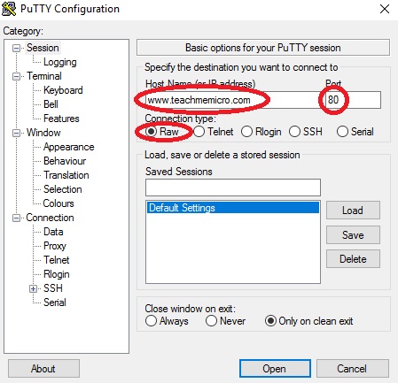
You can send your own HTTP request using Putty. Open Putty, select Raw and provide the hostname or IP address and the port number. Here it's set to hostname: www.teachmemicro.com, port: 80:
Type your HTTP request on notepad or any other word processor. Copy and paste what you have typed on the Putty terminal. You can also type directly into the terminal if you want. Here's an example request you can enter:
GET / HTTP/1.1
Host: www.teachmemicro.com
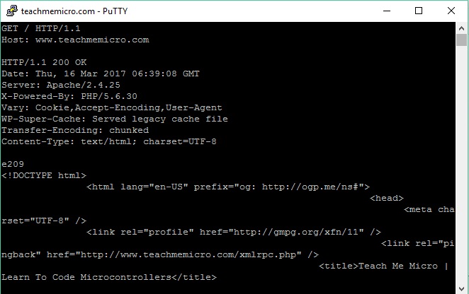
The server will then with the HTTP header and the HTML of the page you requested.
Connecting the PIC to the ESP8266
As mentioned above, the ESP8266 runs on 3.3V while the PIC runs on 5 V so we need some way to convert the voltage levels. Thankfully, we only need to convert data from PIC to ESP8266 (5 to 3.3) because the PIC can recognize 3.3V as logic high. I used a simple voltage divider to convert 5V to 3.3V:

The ESP8266 can accept up to 3.6V so the 3.4375V that this circuit gives is safe.
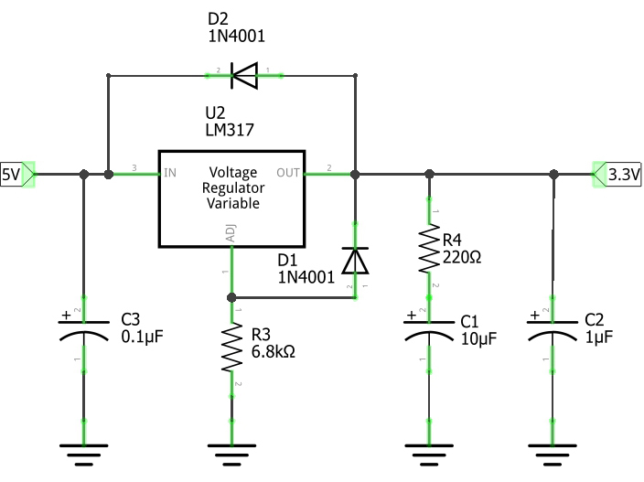
But the circuit above is only useful for logic levels! We still need a 3.3V source to power the ESP8266. You can use an LM317 for that:
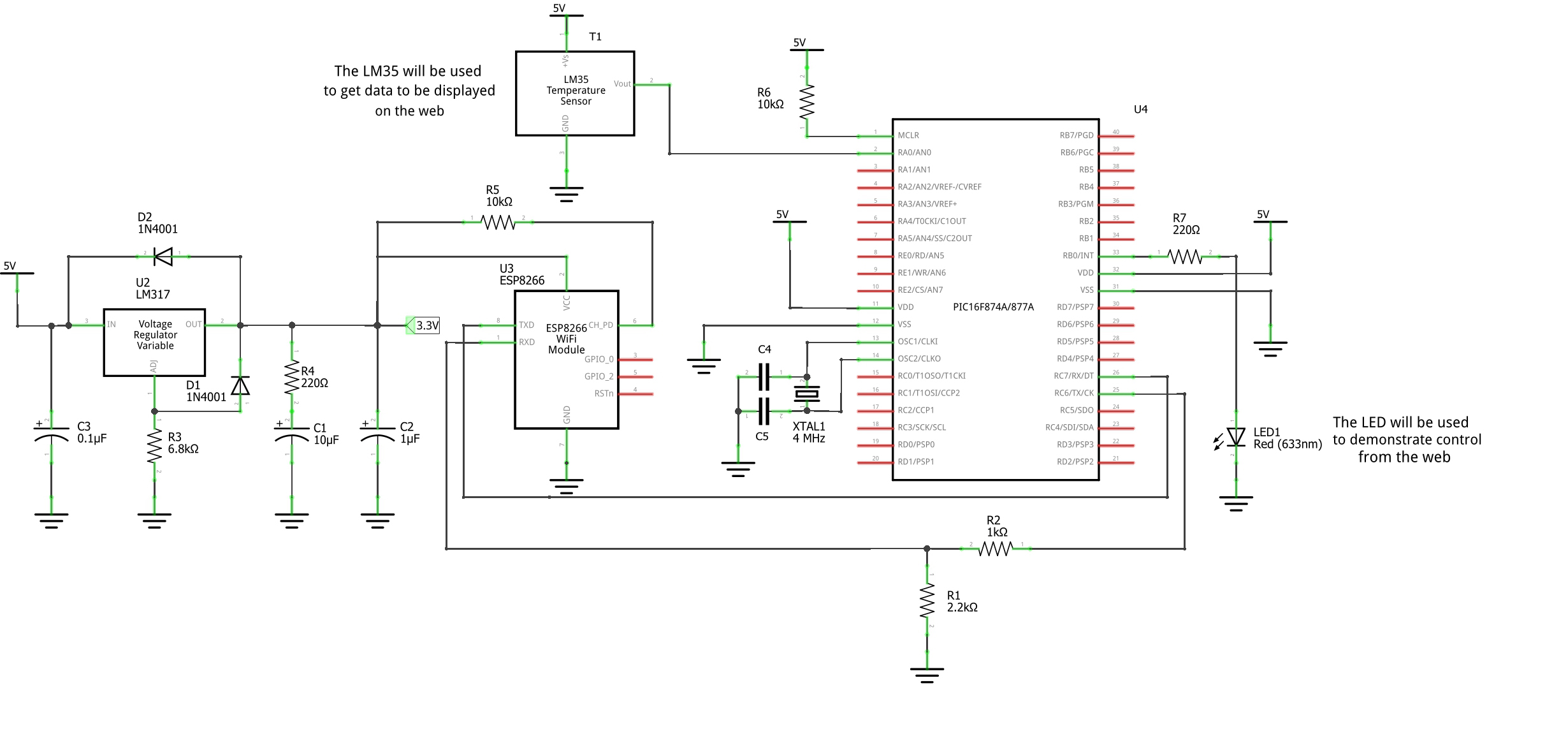
Here's now the complete circuit for this tutorial:
Turning On/Off LED Via Web
Now that we have ourselves a working circuit, it's time to control a LED using buttons on a web page. You need to learn some basic web programming skills but HTML and PHP is a bit beyond the scope of this tutorial so you may need to find another tutorial for that. I highly recommend this website: W3 HTML tutorial W3 PHP tutorial.
I also used Wampserver so that my Windows computer can act as the web server. You can download it here.
Once you have Wampserver installed and running, locate the "www" Wampserver folder. Usually its at C:\\wamp64\www. This is the root folder of the local web server.
I created a php file on the folder specified above.
Control.php:
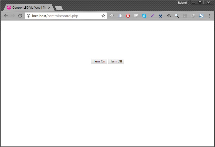
<!doctype html>

<html lang="en">
<head>
  <title>Control LED Via Web | Teach Me Micro</title>
</head>

<body>
<div style="text-align:center;width:80%; margin-left:auto; margin-right:auto;margin-top:150px;">
	<form method="post" action="control.php">
		<input style="margin:auto;"  type="submit" id="on" name="on" value="Turn On" />
		<input style="margin:auto;" margin-right:auto;" type="submit" id="off" name="off" value="Turn Off" />
	</form>
</div>
<?php
if(isset($_POST['on']) || isset($_POST['off'])){
		if(isset($_POST['on'])){
			$textfile = "LEDstate.txt"; // Declares the name and location of the .txt file
			$fileLocation = "$textfile";
			$fh = fopen($fileLocation, 'w   ') or die("Something went wrong!"); // Opens up the .txt file for writing and replaces any previous content
			$stringToWrite = "xonn"; // Write either 1 or 0 depending on request from index.html
			fwrite($fh, $stringToWrite); // Writes it to the .txt file
			fclose($fh);
		}elseif(isset($_POST['off'])){
			$textfile = "LEDstate.txt"; // Declares the name and location of the .txt file
			$fileLocation = "$textfile";
			$fh = fopen($fileLocation, 'w   ') or die("Something went wrong!"); // Opens up the .txt file for writing and replaces any previous content
			$stringToWrite = "xoff"; // Write either 1 or 0 depending on request from index.html
			fwrite($fh, $stringToWrite); // Writes it to the .txt file
			fclose($fh);
		}
}
?>
</body>

</html>
What this code does is create two buttons with labels "on" and "off". If the "on" button is pressed, the string "xonn" is written on the LEDstate.txt file (which, btw, you also need to create on the same folder). Pressing the "off" button writes the string "xoff" on the same text file. I used an "x" as a simple flag to avoid reading errors. Also, I used two n's so that it will have the same length as "off". Note that you can write any text to symbolize on and off. A simpler approach would be writing 1 for on and 0 for off.
Open the above code using your browser in the address "localhost/control.php":
Now for the PIC16F877 part - a PIC Basic code that turns on/off a LED using the serial port.
PIC PBP Code to Receive Data from Web:
' Name        : ledviaweb.pbp
' Compiler    : PICBASIC PRO Compiler 2.6
' Assembler   : PM or MPASM
' Target PIC  : 16F877A
' Hardware    : Non specific
' Oscillator  : 4MHz external crystal or resonator
' Description : PICBASIC PRO program to receive control string from web vie ESP8266

DEFINE HSER_TXSTA 24h
define HSER_RCSTA 90h
define HSER_BAUD 9600

resp var byte
command var byte[3]

TRISB = 0

main:
hserout ["AT",13,10]                        'send AT to ESP8266 and wait for OK
hserin 5000,main,[wait("O"), resp]
if resp = "K" then goto startConnection
pause 3000
goto main

startConnection:
pause 1000
hserout["AT+CWMODE=3",13,10]   'set to dual mode
pause 1000
hserout["AT+CWJAP=",44,34,"cetfaculty",34,44,34,"123456",34,13,10]   'connect to WiFi
pause 1000
hserout ["AT+CIPSTART=0",34,44,34,"TCP",34,44,34,"localhost",34,44,34,"80",34,13,10]    'establish TCP connection
pause 1000
hserout ["AT+CIPSEND=0",44,"16",13,10]      'send data
pause 1000
hserout ["GET /LEDstate.txt",13,10]         'use HTTP GET to acquired LEDstate.txt file
pause 1000

waitForReply:
hserin 1000,waitForReply,[wait("x"), STR command \3\13]
if command[0] = "o" and command[1] = "n" and command[2] = "n" then
    PORTB.0 = 1
else
    if command = "o" and command[1] = "f" and command[2] = "f" then
        PORTB.0 = 0
    endif
endif
pause 2000
goto main
End
The PIC16F877 first sends the string "AT" to the ESP8266 to check if the communication is alive. If it is alive, the ESP would reply with "OK" and then the PIC16F877 Internet connection starts and sends HTTP requests. It then waits for the character "x" from the web server's reply. If the character "x" is followed by the character "o" and two "n's", then the "on" command was issued. Alternatively, if the character "x" follows the character "o" then two "f's" then "off" command was issued.
Sending Data to the Web
The next part of this tutorial is displaying data from the PIC's analog to digital converter (ADC) module to a webpage.
PIC16F877 PBP Code to Send Data to Web:
' Name        : adctoweb.pbp
' Compiler    : PICBASIC PRO Compiler 2.6
' Assembler   : PM or MPASM
' Target PIC  : 16F877A
' Hardware    : Non specific
' Oscillator  : 4MHz external crystal or resonator
' Description : PICBASIC PRO program to send adc values to web server
'
DEFINE HSER_TXSTA 24h
define HSER_RCSTA 90h
define HSER_BAUD 9600

Define  ADC_BITS     10    ' Set number of bits in result
Define  ADC_CLOCK    3     ' Set clock source (3=rc)
Define  ADC_SAMPLEUS 50    ' Set sampling time in uS

resp var byte
resp2 var byte
adval var word
temp var word
command var byte[3]

TRISB = 0
TRISA = %11111111
ADCON1 = %10000010

readValue:
adcin 0, adval
temp = adval*100/205
pause 100

main:
hserout ["AT",13,10]                              'send AT to ESP8266 and wait for OK
hserin 5000,main,[wait("O"), resp]
if resp = "K" then goto startConnection
pause 3000
goto main

startConnection:
pause 1000
hserout["AT+CWMODE=3",13,10]                        'set to dual mode
pause 1000
hserout["AT+CWJAP=",44,34,"cetfaculty",34,44,34,"123456",34,13,10]      'connect to WiFi
pause 1000
hserout ["AT+CIPSTART=0",34,44,34,"TCP",34,44,34,"localhost",34,44,34,"80",34,13,10]        'establish TCP connection
pause 1000
hserout ["AT+CIPSEND=0",44,"16",13,10]        'send data
pause 1000
hserout ["POST /read.php",13,10]
hserout ["Host: localhost",13,10]
hserout ["User-Agent: Mozilla",13,10]
hserout ["Content-Type: application/x-www-form-urlencode",13,10]
hserout ["Content-Length: "]
if temp > 0 && temp < 9 then
    hserout ["7",13,10]
else
    if temp > 9 && temp < 99 then
        hserout ["8",13,10]
    else
        if temp > 99 && temp < 999 then
            hserout ["9",13,10]
        else
            if temp > 999 then
                hserout ["10",13,10]
            endif
        endif
    endif
endif
hserout [13,10]
hserout ["value=",dec temp,13,10,13,10]
pause 1000

waitForReply:
PORTB.0 = 0
hserin 1000,waitForReply,[wait("O"), resp2]
if resp2 = "K" then
    PORTB.0 = 1
endif
pause 2000
goto readValue
End
First, we need to read the ADC value. That value is then included in the POST request.
Example POST request:
POST /read.php HTTP/1.1
Host: localhost
User-Agent: Mozilla
Content-Type: application/x-www-form-urlencoded
Content-length: 9

value=500
HTTP POST is much more strict hence there are lots of headers included. Noticed also how long it took to specify the content length as PBP doesn't have a length() function.
Next is the web page part. Here we need three files: one PHP file to display the values (index.php), another PHP file to capture the values (read.php) and a text file named "values.txt" to store the last captured value.
Read.php:
<?php

$value = $_POST['value'];

$textfile = "values.txt"; // Declares the name and location of the .txt file
$fileLocation = "$textfile";
$fh = fopen($fileLocation, 'w') or die("Something went wrong!"); // Opens up the .txt file for writing and replaces any previous content
fwrite($fh, $value); // Writes it to the .txt file
fclose($fh);

?>
The data we posted is in the $_POST['value'] variable which is then passed to the $value variable. That value is then stored into the text file "values.txt".
Index.php:
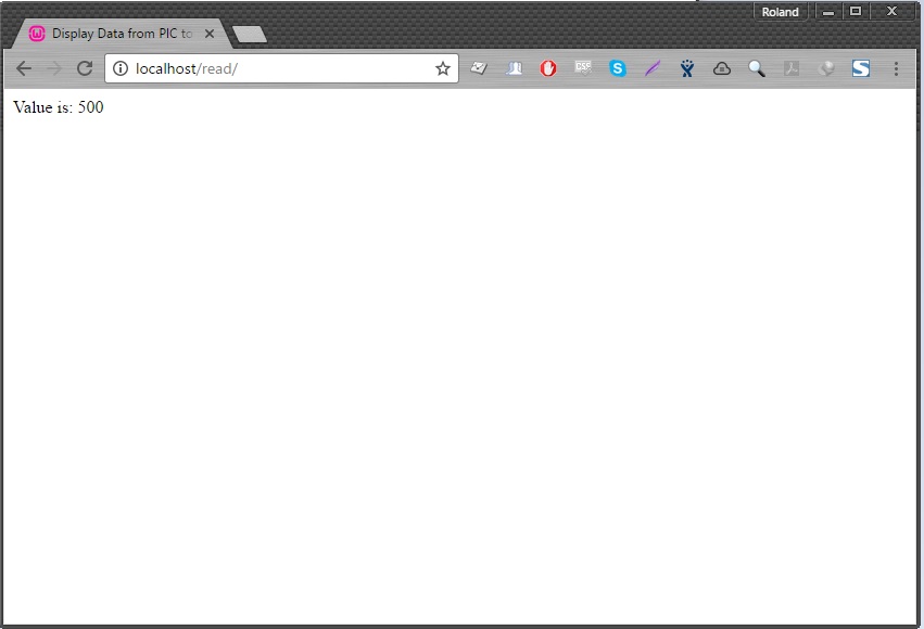
<!doctype html>

<html lang="en">
<head>
  <title>Display Data from PIC to Web</title>
</head>

<body>
	<?php
	$textfile = "values.txt"; // Declares the name and location of the .txt file
	//$fileLocation = "$textfile";
	$fh = fopen($textfile, 'r') or die("Something went wrong!"); // Opens up the .txt file for writing and replaces any previous content
	$value = fread($fh,3);
	fclose($fh);

	printf("Value is: %s",$value);
	?>
</body>
</html>
This is a simple page that reads the string inside "values.txt" and prints it on the web page:
Comments and questions about this PIC16F877 Internet tutorial is highly appreciated. Kindly drop them down below!


Great tutorial! Can You send me a scheme circuit in bigger format, this attached is too small resolution. Thanks
Hi I can not get any kind of ok message with esp8266. Is the program in question problematic?
Hello,
I'm trying to use esp8266 to export data from a device. I need the return to know if the data was exported correctly and also need to be able to update the wifi password, if necessary. I thought that this example would fit perfectly in my need, with some adaptations. The problem is that I use the ccs compiler c. Could you convert this code to ccs? grateful and waiting, Sergio - sergiobombac@gmail.com
HI guys i am a biginner i would like to know if i wrote my code in asm as i used to do . now i would like to know if it possible to write the code in asm code and then write esp8266 in AT command
because i am not good at using c language to write code