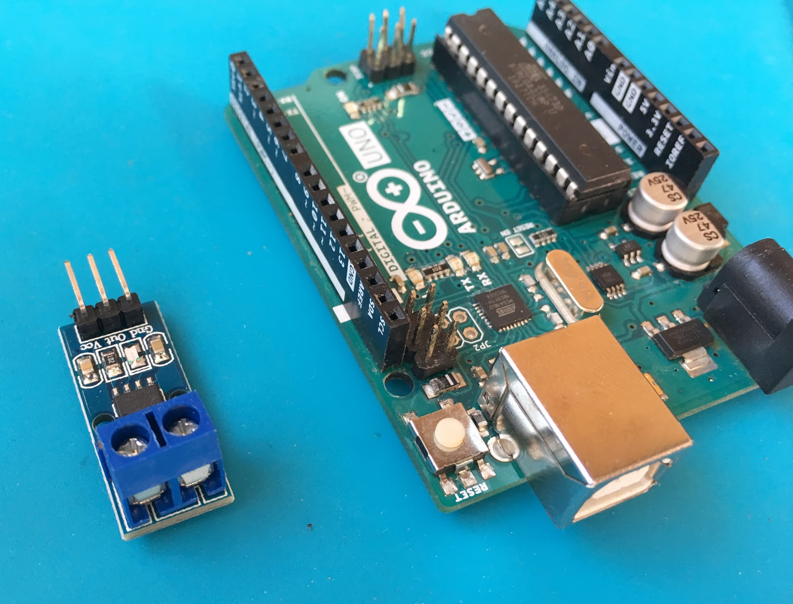
A current sensor lets an Arduino measure how much current flows through a wire, motor, LED strip, battery-powered circuit, or power supply load. In this tutorial, you will learn how to use an ACS712 current sensor with Arduino to measure DC current and display the result on the Serial Monitor.
The ACS712 is a popular current sensor module because it is inexpensive, easy to wire, and works with the Arduino’s analog input pins. However, the output is not a direct “current value.” Instead, the sensor produces an analog voltage that must be converted into amperes using the correct formula.
By the end of this guide, you will know how the ACS712 works, how to wire it safely, how to calculate current from the analog reading, and how to improve the stability of your measurements.
What Is a Current Sensor?
A current sensor is a device that measures the amount of electric current flowing through a conductor. Current sensors are useful in many electronics and Arduino projects, including:
- Battery monitoring
- Solar power monitoring
- Motor current measurement
- Over-current detection
- Power supply testing
- LED strip current measurement
- Energy monitoring projects
For Arduino projects, one of the most common current sensor modules is the ACS712 Hall-effect current sensor.
What Is the ACS712 Current Sensor?
The ACS712 is a Hall-effect-based current sensor. It measures current by detecting the magnetic field produced when current flows through its internal conductor.
When current passes through the ACS712, it creates a magnetic field. The internal Hall-effect sensor detects this magnetic field and converts it into an output voltage. The Arduino reads that voltage using one of its analog input pins.
In simple terms, the ACS712 converts:
current → magnetic field → output voltage → Arduino ADC value
The Arduino can then convert the ADC value back into current using a formula.
ACS712 Module Pins
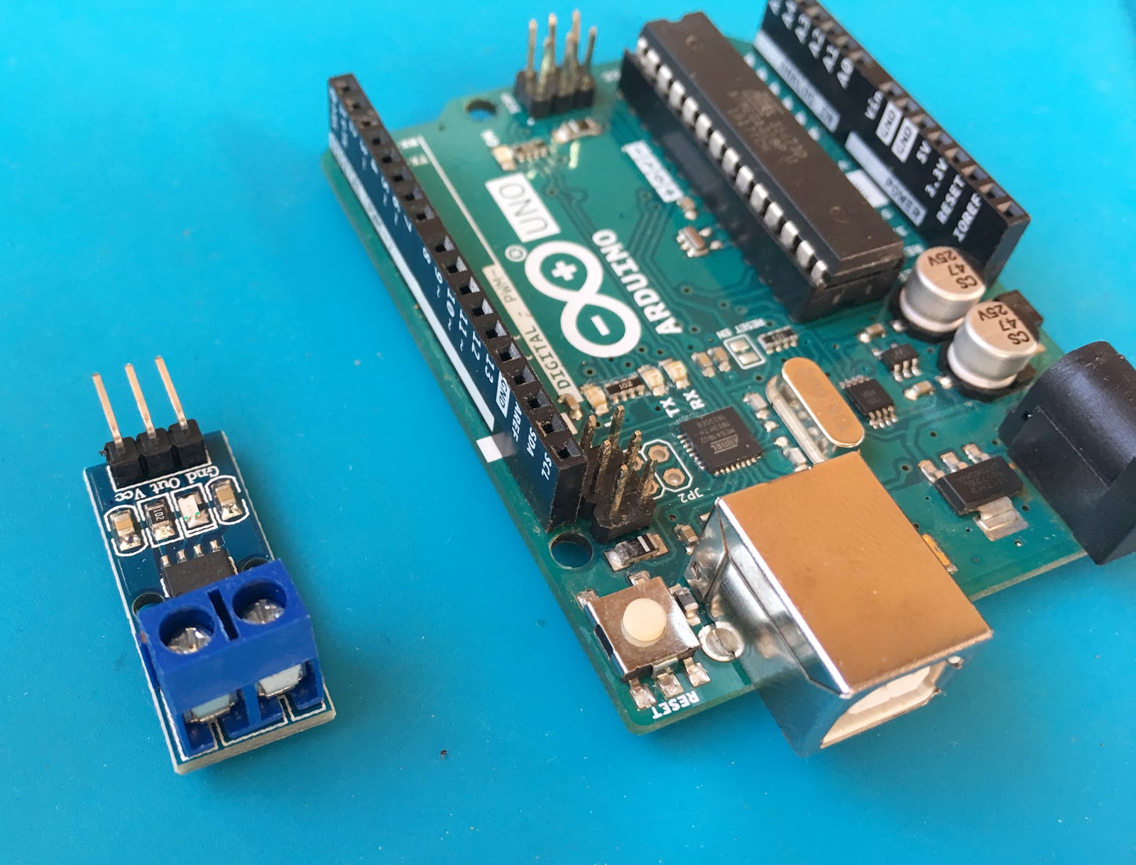
Most ACS712 modules have two sides: the low-current signal side and the high-current screw terminal side.
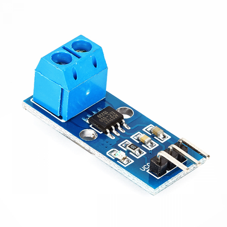
The signal side usually has three pins:
| Pin | Description |
|---|---|
| VCC | Connects to Arduino 5V |
| GND | Connects to Arduino GND |
| OUT | Analog output connected to an Arduino analog input |
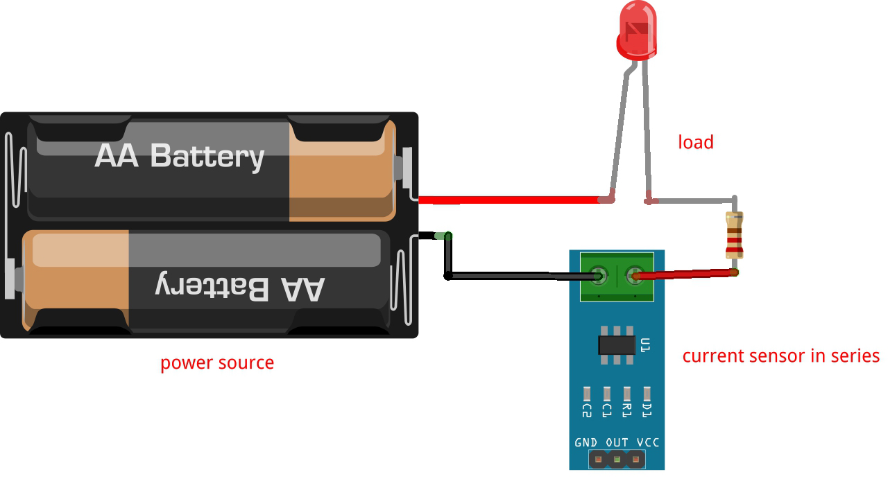
The screw terminal side is where the measured current passes through. The current sensor must be connected in series with the load, similar to how an ammeter is connected.
For example, if you want to measure the current flowing through a DC motor, the sensor should be placed in series between the power supply and the motor.
ACS712 Versions and Sensitivity
The ACS712 comes in different current ranges. Each version has a different sensitivity.
| ACS712 Version | Current Range | Sensitivity |
|---|---|---|
| ACS712-05B | ±5 A | 185 mV/A |
| ACS712-20A | ±20 A | 100 mV/A |
| ACS712-30A | ±30 A | 66 mV/A |
The sensitivity tells you how much the output voltage changes for every ampere of current.
For example, the ACS712-05B has a sensitivity of 185 mV per ampere, or:
0.185 V/A
This means that for every 1 A of current, the output voltage changes by about 0.185 V from the zero-current voltage.
How the ACS712 Output Works
The ACS712 output is centered around half of the supply voltage.
If the sensor is powered by 5 V, the output voltage is usually around:
5 V / 2 = 2.5 V
This is the zero-current voltage.
When current flows in one direction, the output voltage rises above 2.5 V. When current flows in the opposite direction, the output voltage drops below 2.5 V.
That means the ACS712 can measure both positive and negative current.
For a 5 V Arduino and an ACS712-05B:
- No current: about 2.5 V
- Positive current: above 2.5 V
- Negative current: below 2.5 V
Because of this, the correct current formula is:
current = (sensorVoltage - zeroCurrentVoltage) / sensitivity;
For the 5A version:
current = (sensorVoltage - 2.5) / 0.185;
However, in real circuits, the zero-current voltage is not always exactly 2.5 V. Therefore, it is better to calibrate the sensor first.
Arduino ACS712 Wiring
Connect the ACS712 module to the Arduino as follows:
| ACS712 Pin | Arduino Pin |
|---|---|
| VCC | 5V |
| GND | GND |
| OUT | A0 |
Then connect the screw terminals in series with the load you want to measure.
For a simple DC load, the connection is:
Power Supply Positive → ACS712 Input → ACS712 Output → Load Positive
Load Negative → Power Supply Negative
The Arduino side and the load side are electrically isolated inside the ACS712 chip by the Hall-effect sensing method, but you should still follow safe wiring practices, especially when measuring higher currents.
Important Safety Notes
The ACS712 module is often used in low-voltage Arduino projects, but some modules are advertised for AC mains measurement. Be very careful with that.
If you are a beginner, do not connect the ACS712 module directly to mains voltage. Exposed screw terminals, thin PCB traces, and poor module spacing can be dangerous. For learning and testing, start with low-voltage DC loads such as motors, lamps, resistors, or LED strips powered from a battery or bench power supply.
Also, make sure the expected current does not exceed the rating of your ACS712 module.
Testing the Sensor with AnalogReadSerial
Before calculating current, test the sensor output using the built-in Arduino example.
Open:
File > Examples > Basics > AnalogReadSerial
Upload the sketch and open the Serial Monitor.
With the ACS712 output connected to A0 and no current flowing, the reading should be close to 512 on a 10-bit Arduino ADC.
That value corresponds to about 2.5 V when using a 5 V reference:
2.5 V ≈ 512 ADC counts
The value may not be exactly 512, and that is normal. Sensor tolerance, supply voltage, electrical noise, and ADC variation can shift the zero-current point.
Basic Arduino Code for ACS712 DC Current Measurement
This example reads the ACS712 output, averages several samples, and converts the result into current.
This code is for the ACS712-05B 5A version. If you are using the 20A or 30A version, change the sensitivity value.
/*
  Arduino Current Sensor Tutorial using ACS712
  Measures DC current using an ACS712 current sensor module.

  ACS712-05B sensitivity: 0.185 V/A
  ACS712-20A sensitivity: 0.100 V/A
  ACS712-30A sensitivity: 0.066 V/A
*/

#define SENSOR_PIN A0
#define SAMPLES 100

const float ADC_REFERENCE = 5.0;
const float ADC_RESOLUTION = 1023.0;

// Change this depending on your ACS712 version:
// 5A  version: 0.185 V/A
// 20A version: 0.100 V/A
// 30A version: 0.066 V/A
const float SENSITIVITY = 0.185;

float zeroCurrentVoltage = 2.5;

void setup() {
  Serial.begin(9600);

  Serial.println("ACS712 Arduino Current Sensor");
  Serial.println("Calibrating zero-current voltage...");

  zeroCurrentVoltage = calibrateZeroCurrent();

  Serial.print("Zero-current voltage: ");
  Serial.print(zeroCurrentVoltage, 3);
  Serial.println(" V");
}

void loop() {
  float sensorVoltage = readAverageVoltage();
  float current = (sensorVoltage - zeroCurrentVoltage) / SENSITIVITY;

  Serial.print("Voltage: ");
  Serial.print(sensorVoltage, 3);
  Serial.print(" V");

  Serial.print(" | Current: ");
  Serial.print(current, 3);
  Serial.println(" A");

  delay(500);
}

float readAverageVoltage() {
  long adcTotal = 0;

  for (int i = 0; i < SAMPLES; i++) {
    adcTotal += analogRead(SENSOR_PIN);
    delay(1);
  }

  float adcAverage = adcTotal / (float)SAMPLES;
  float voltage = (adcAverage * ADC_REFERENCE) / ADC_RESOLUTION;

  return voltage;
}

float calibrateZeroCurrent() {
  return readAverageVoltage();
}
How the Code Works
First, the Arduino reads the analog voltage from the ACS712 OUT pin:
analogRead(SENSOR_PIN);
On an Arduino Uno, Nano, or Mega,
analogRead()Next, the code converts the ADC value into voltage:
float voltage = (adcAverage * ADC_REFERENCE) / ADC_RESOLUTION;
If the Arduino uses a 5 V reference, an ADC value near 512 is about 2.5 V.
Then the code subtracts the zero-current voltage:
sensorVoltage - zeroCurrentVoltage
This step is important. Without subtracting the zero-current voltage, the calculation will be wrong because the ACS712 output is centered around half of VCC.
Finally, the result is divided by the sensor sensitivity:
current = (sensorVoltage - zeroCurrentVoltage) / SENSITIVITY;
For the 5A version, the sensitivity is 0.185 V/A.
Using the ACS712 20A or 30A Version
If your module is not the 5A version, change this line:
const float SENSITIVITY = 0.185;
Use one of these values instead:
const float SENSITIVITY = 0.100; // ACS712-20A
const float SENSITIVITY = 0.066; // ACS712-30A
The wiring stays the same, but the conversion factor changes.
Why Calibration Is Important
The ideal zero-current voltage is VCC/2. For a 5 V Arduino, that is 2.5 V.
However, the real value may be slightly different. For example, your sensor may output 2.48 V or 2.52 V when no current is flowing.
That small difference matters. If you ignore it, your current reading may show a false positive or false negative current even when the load is off.
The example sketch solves this by measuring the zero-current voltage during startup:
zeroCurrentVoltage = calibrateZeroCurrent();
For best results, make sure no current is flowing through the sensor when the Arduino starts.
Why the Reading Is Noisy
The ACS712 can be noisy because it outputs a small analog voltage change. For the 5A version, 1 A only changes the output by 0.185 V. Smaller currents produce even smaller changes.
Noise may come from:
- Arduino ADC resolution
- USB power noise
- Long wires
- Breadboard connections
- Switching power supplies
- Motor electrical noise
- Sensor offset drift
Averaging multiple readings helps reduce noise. In the example code, this line controls how many samples are averaged:
#define SAMPLES 100
A higher value gives a steadier reading, but it also makes the response slower.
Measuring Small Currents
The ACS712 is not ideal for very small currents. Although it can detect changes, the noise level may make low-current readings unstable.
For example, measuring a few milliamps may be difficult with an ACS712, especially with the 20A or 30A version. If you need to measure small currents accurately, a shunt resistor current sensor or a dedicated current monitor such as the INA219 or INA226 may be a better choice.
Use the ACS712 when you need a simple Arduino current sensor for moderate DC loads such as motors, LED strips, and power supply outputs.
Measuring AC Current with ACS712
The ACS712 can also detect bidirectional current, so it can be used for AC current measurement. However, the code is different.
For AC current, you cannot simply read one analog value and convert it to current. Instead, you need to sample the waveform and calculate RMS current.
The general steps are:
- Read many samples over at least one AC cycle.
- Subtract the zero-current offset from each sample.
- Square each current sample.
- Average the squared values.
- Take the square root of the average.
That gives the RMS current.
For beginner projects, start with DC current measurement first. Once the DC version works, you can move on to AC RMS measurement.
Troubleshooting
The Serial Monitor Shows Current Even with No Load
This usually means the zero-current voltage is not calibrated correctly. Make sure no current is flowing through the ACS712 when the Arduino starts.
You can also increase the number of samples to reduce noise.
The Current Reading Is Negative
The current may be flowing in the opposite direction through the sensor. Reverse the load connections on the screw terminal side, or treat the negative value as direction information.
The Reading Is Unstable
Try these fixes:
- Use shorter wires
- Average more samples
- Use a stable 5 V supply
- Keep motor wires away from the sensor output wire
- Add filtering in software
- Avoid loose breadboard connections
The Reading Is Too High or Too Low
Check that the sensitivity value matches your ACS712 version. The 5A, 20A, and 30A modules use different sensitivity values.
Also, measure the Arduino 5 V pin with a multimeter. If the actual voltage is not exactly 5 V, update the ADC_REFERENCE value in the sketch.
ACS712 vs INA219
The ACS712 is not the only current sensor you can use with Arduino. Another popular option is the INA219.
| Sensor | Output Type | Best For |
|---|---|---|
| ACS712 | Analog voltage | Simple current sensing, higher current loads, bidirectional current |
| INA219 | I2C digital output | More accurate low-current DC measurement, voltage and power monitoring |
Choose the ACS712 if you want a simple analog current sensor. Choose the INA219 if you need more accurate DC current, voltage, and power readings.
Conclusion
The ACS712 is one of the easiest current sensors to use with Arduino. It connects to a single analog input pin and can measure current by producing a voltage proportional to the current flowing through its terminals.
The most important thing to remember is that the ACS712 output is centered around half of VCC. Therefore, you must subtract the zero-current voltage before dividing by the sensor sensitivity.
For the ACS712-05B version, the formula is:
current = (sensorVoltage - zeroCurrentVoltage) / 0.185;
Once calibrated, the ACS712 can be used in Arduino projects such as motor monitoring, battery-powered circuits, LED strip current measurement, and simple over-current protection systems.