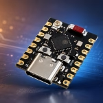
The ESP32-S3 Mini, often sold as the ESP32-S3 Super Mini, packs a surprisingly powerful ESP32-S3 microcontroller into a board only slightly larger than its USB-C connector. Despite its size, the board gives you a dual-core processor, Wi-Fi, Bluetooth Low Energy, native USB, PSRAM on some versions, and enough GPIO pins for many embedded projects.
There is one problem: documentation for these generic Super Mini boards is often incomplete. Different online sellers sometimes show different pin diagrams, memory specifications, and even different onboard LED connections.
In this guide, I will show you how to set up the ESP32-S3 Super Mini in the Arduino IDE, identify the hardware you actually received, test its flash and PSRAM, and control the onboard RGB LED. We will also look at the pinout and some common upload problems.
What is the ESP32-S3 Mini?
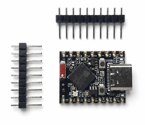
The ESP32-S3 Super Mini is a small third-party development board built around the ESP32-S3 microcontroller. The ESP32-S3 itself uses two Xtensa LX7 CPU cores running at up to 240 MHz and includes 2.4 GHz Wi-Fi and Bluetooth Low Energy.
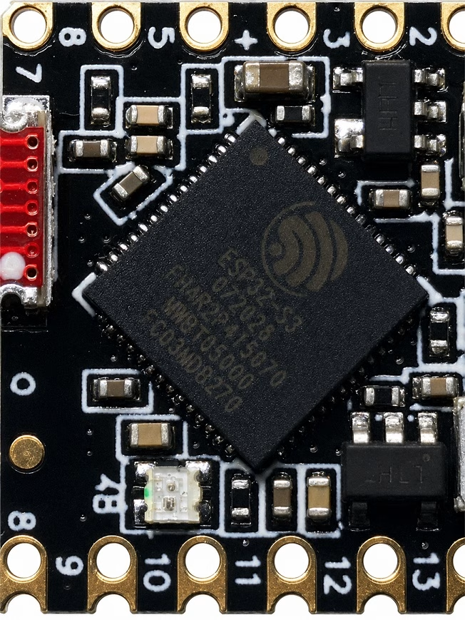
The particular Super Mini version commonly sold online uses an ESP32-S3FH4R2. The letters at the end are important:
- F - the chip contains flash memory.
- H4 - 4 MB of flash is integrated into the package.
- R2 - 2 MB of PSRAM is integrated into the package.
This makes the small board considerably more capable than its physical size suggests. In particular, the PSRAM can be useful for frame buffers, image processing, web applications, and other programs that need more working memory than the ESP32-S3's internal RAM can comfortably provide.
However, not every board advertised as an "ESP32-S3 Mini" necessarily contains the same chip. Before relying on the memory specifications printed by a seller, I recommend checking the marking on the ESP32-S3 itself and then verifying the memory through software.
ESP32-S3 Mini vs ESP32-S3-MINI-1
There is also an official Espressif product named the ESP32-S3-MINI-1. Do not confuse this with the ESP32-S3 Super Mini development board shown in this tutorial.
The ESP32-S3-MINI-1 is an Espressif module intended to be soldered into another PCB. The ESP32-S3 Super Mini, meanwhile, is a complete development board with a USB-C connector, voltage regulator, buttons, and exposed pins.
Online stores sometimes shorten both names to "ESP32-S3 Mini", which is why the terminology can be confusing.
ESP32-S3 Super Mini Specifications
For the common ESP32-S3FH4R2-based version, the important specifications are:
| Feature | ESP32-S3 Super Mini |
|---|---|
| Microcontroller | ESP32-S3 |
| CPU | Dual-core Xtensa LX7 |
| Maximum CPU Frequency | 240 MHz |
| Internal SRAM | 512 KB |
| Flash | 4 MB on ESP32-S3FH4R2 version |
| PSRAM | 2 MB QSPI on ESP32-S3FH4R2 version |
| Wi-Fi | 2.4 GHz 802.11 b/g/n |
| Bluetooth | Bluetooth Low Energy |
| USB | Native USB through USB-C |
| Logic Voltage | 3.3 V |
| Onboard RGB LED | Typically WS2812 on GPIO48 |
The 3.3 V logic level is worth remembering. Do not apply 5 V directly to an ESP32-S3 GPIO pin.
ESP32-S3 Super Mini Pinout
The compact Super Mini board exposes fewer pins than a full-size ESP32-S3 development board. This is one of the compromises required to make the board so small.
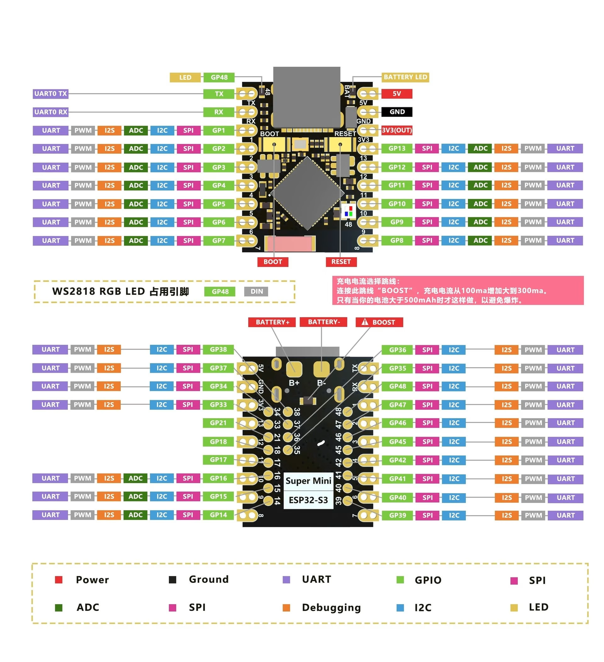
The version used for this guide has GPIO1 through GPIO13 together with the default UART TX and RX pins.
| Board Label | ESP32-S3 GPIO | Useful Functions | Notes |
|---|---|---|---|
| TX | GPIO43 | UART TX, digital I/O | Default UART0 transmit pin |
| RX | GPIO44 | UART RX, digital I/O | Default UART0 receive pin |
| 1 | GPIO1 | ADC, touch, PWM, digital I/O | Good general-purpose pin |
| 2 | GPIO2 | ADC, touch, PWM, digital I/O | Good general-purpose pin |
| 3 | GPIO3 | ADC, touch, PWM, digital I/O | Strapping pin; use with some care at boot |
| 4 | GPIO4 | ADC, touch, PWM, digital I/O | Good general-purpose pin |
| 5 | GPIO5 | ADC, touch, PWM, digital I/O | Good general-purpose pin |
| 6 | GPIO6 | ADC, touch, PWM, digital I/O | Good general-purpose pin |
| 7 | GPIO7 | ADC, touch, PWM, digital I/O | Good general-purpose pin |
| 8 | GPIO8 | ADC, touch, PWM, digital I/O | Useful for I2C |
| 9 | GPIO9 | ADC, touch, PWM, digital I/O | Useful for I2C |
| 10 | GPIO10 | ADC, touch, PWM, digital I/O | General-purpose |
| 11 | GPIO11 | ADC, touch, PWM, digital I/O | ADC2 channel |
| 12 | GPIO12 | ADC, touch, PWM, digital I/O | ADC2 channel |
| 13 | GPIO13 | ADC, touch, PWM, digital I/O | ADC2 channel |
| RGB | GPIO48* | WS2812 RGB LED | Onboard; not normally exposed |
*GPIO48 is commonly used for the RGB LED on this Super Mini layout. Generic boards can vary, so check your board if the RGB example later in this guide does not work.
Where are GPIO19 and GPIO20?
The ESP32-S3 has native USB support. GPIO19 and GPIO20 can serve as the USB D- and D+ signals, respectively. On this board, the USB-C connector already uses the ESP32-S3's USB interface, so these pins are not presented like ordinary header pins.
This native USB connection is one of the reasons the Super Mini can be made so small: it does not necessarily need a separate CH340, CP2102, or other USB-to-UART converter.
Which Pins Should Beginners Use?
For initial projects, I would start with GPIO1, GPIO2, GPIO4, GPIO5, GPIO6, GPIO7, GPIO8, GPIO9, GPIO10, GPIO11, GPIO12 or GPIO13.
GPIO3 is usable, but it is also one of the ESP32-S3's strapping pins. A circuit that forces an inappropriate logic level on a strapping pin during reset can change the way the microcontroller boots.
Installing ESP32-S3 Support in Arduino IDE
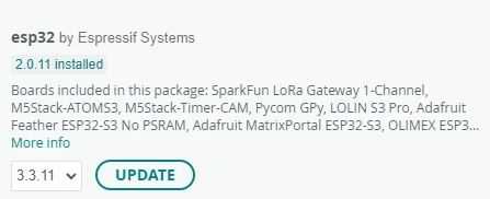
If you have already programmed another ESP32 board using the Arduino IDE, you may already have Espressif's Arduino core installed. Otherwise, install the ESP32 package using the Arduino IDE's Boards Manager.
- Open the Arduino IDE.
- Open Boards Manager.
- Search for esp32.
- Install the package published by Espressif Systems.
- Restart the Arduino IDE if necessary.
The generic Super Mini normally does not have its own entry in the Arduino board list. Instead, select:
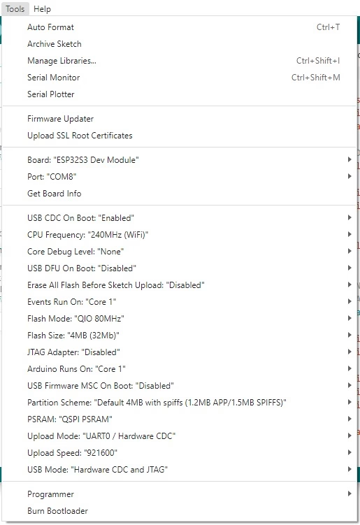
Tools > Board > ESP32 Arduino > ESP32S3 Dev ModuleThis gives us access to the configuration options needed for the S3.
Recommended Arduino IDE Settings
For a common ESP32-S3FH4R2 Super Mini, I recommend starting with these settings:
| Arduino IDE Setting | Value |
|---|---|
| Board | ESP32S3 Dev Module |
| CPU Frequency | 240MHz |
| USB CDC On Boot | Enabled |
| Flash Size | 4MB (32Mb) |
| Flash Mode | QIO |
| PSRAM | QSPI PSRAM |
| Partition Scheme | Default 4MB with SPIFFS |
| Upload Mode | UART0 / Hardware CDC |
QSPI PSRAM is especially important. The ESP32-S3FH4R2 contains 2 MB of Quad SPI PSRAM. Selecting the wrong PSRAM type can prevent the board from booting correctly or cause the PSRAM test to fail.
Why Enable USB CDC On Boot?
On many older ESP32 boards, a separate USB-to-serial IC creates the COM port. The ESP32-S3 can instead expose a serial interface directly through its internal USB hardware.
With USB CDC On Boot = Enabled, calls such as:
Serial.println("Hello");can appear directly in the Arduino Serial Monitor through the USB-C connection.
If your sketch uploads correctly but the Serial Monitor remains completely blank, this setting is one of the first things I would check.
First Test: Serial Output
Before testing anything more complicated, let's confirm that the microcontroller can run a sketch and communicate with the computer.
void setup() {
  Serial.begin(115200);

  delay(2000);

  Serial.println();
  Serial.println("ESP32-S3 Super Mini is running!");
}

void loop() {
  Serial.println("Hello from ESP32-S3");
  delay(1000);
}
Upload the program and open the Serial Monitor at 115200 baud.
You should see something similar to:
ESP32-S3 Super Mini is running!
Hello from ESP32-S3
Hello from ESP32-S3
Hello from ESP32-S3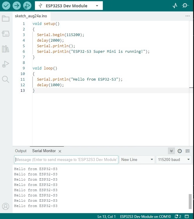
If this works, we have already confirmed three things: the ESP32-S3 is running, USB programming works and USB serial output works.
Testing the ESP32-S3 Mini Flash and PSRAM
One specification I would definitely verify on a generic ESP32-S3 Super Mini is its memory. Fortunately, Arduino gives us functions that can report the flash and PSRAM sizes directly.
Upload the following program:
#include <Arduino.h>

void setup() {
  Serial.begin(115200);
  delay(2000);

  Serial.println("ESP32-S3 Hardware Test");
  Serial.println("----------------------");

  Serial.print("Chip model: ");
  Serial.println(ESP.getChipModel());

  Serial.print("CPU cores: ");
  Serial.println(ESP.getChipCores());

  Serial.print("CPU frequency: ");
  Serial.print(ESP.getCpuFreqMHz());
  Serial.println(" MHz");

  Serial.print("Flash size: ");
  Serial.print(ESP.getFlashChipSize() / 1024.0 / 1024.0, 2);
  Serial.println(" MB");

  Serial.print("PSRAM detected: ");
  Serial.println(psramFound() ? "YES" : "NO");

  Serial.print("PSRAM size: ");
  Serial.print(ESP.getPsramSize() / 1024.0 / 1024.0, 2);
  Serial.println(" MB");

  Serial.print("Free PSRAM: ");
  Serial.print(ESP.getFreePsram() / 1024);
  Serial.println(" KB");
}

void loop() {
}
Expected Result for the ESP32-S3FH4R2 Version
On a Super Mini that really contains an ESP32-S3FH4R2, the important parts of the result should look approximately like this:
ESP32-S3 Hardware Test
----------------------
Chip model: ESP32-S3
CPU cores: 2
CPU frequency: 240 MHz
Flash size: 4.00 MB
PSRAM detected: YES
PSRAM size: 2.00 MB
Free PSRAM: 2045 KB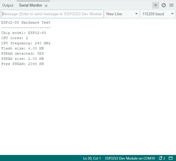
If the program reports PSRAM size: 0 MB, this does not immediately mean your board lacks PSRAM. First verify that:
Tools > PSRAM > QSPI PSRAMis selected.
If PSRAM still does not appear, inspect the marking on the chip. A different ESP32-S3 variant may have been fitted to your board.
Experiment: Actually Allocating Data in PSRAM
Detecting PSRAM is useful, but I also wanted a test that actually writes data to it. The following experiment allocates a 1 MB buffer using PSRAM, fills it with data, and then checks whether the allocation succeeded.
#include <Arduino.h>

const size_t BUFFER_SIZE = 1024 * 1024;

void setup() {
  Serial.begin(115200);
  delay(2000);

  if (!psramFound()) {
    Serial.println("PSRAM not found.");
    return;
  }

  Serial.print("Free PSRAM before allocation: ");
  Serial.print(ESP.getFreePsram());
  Serial.println(" bytes");

  uint8_t *buffer = (uint8_t *)ps_malloc(BUFFER_SIZE);

  if (buffer == NULL) {
    Serial.println("1 MB PSRAM allocation FAILED.");
    return;
  }

  Serial.println("1 MB PSRAM allocation successful.");

  for (size_t i = 0; i < BUFFER_SIZE; i++) {
    buffer[i] = i & 0xFF;
  }

  bool passed = true;

  for (size_t i = 0; i < BUFFER_SIZE; i++) {
    if (buffer[i] != (i & 0xFF)) {
      passed = false;
      break;
    }
  }

  Serial.println(passed ?
                 "PSRAM read/write test PASSED." :
                 "PSRAM read/write test FAILED.");

  Serial.print("Free PSRAM after allocation: ");
  Serial.print(ESP.getFreePsram());
  Serial.println(" bytes");

  free(buffer);
}

void loop() {
}
For a working 2 MB PSRAM device, the 1 MB allocation should succeed. More importantly, the final verification confirms that the data written to the buffer can also be read back correctly.
A successful test should produce something similar to:
Free PSRAM before allocation: 2095103 bytes
1 MB PSRAM allocation successful.
PSRAM read/write test PASSED.
Free PSRAM after allocation: 1046511 bytes
This experiment also demonstrates why PSRAM is useful. A one-megabyte buffer would consume far too much of the ESP32-S3's normal internal RAM, while the external/in-package PSRAM gives memory-hungry applications much more room.
Using the ESP32-S3 Super Mini RGB LED
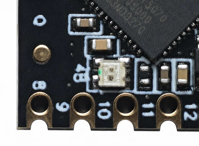
Another nice feature of many ESP32-S3 Super Mini boards is the onboard addressable RGB LED. On the version covered by this guide, the LED is a WS2812-compatible device connected to GPIO48.
An addressable RGB LED is different from three ordinary LEDs. Instead of supplying separate red, green, and blue signals, we send a digital data stream containing the required color.
Installing the NeoPixel Library
Open the Arduino Library Manager and install the Adafruit NeoPixel library.
Then upload this example:
#include <Adafruit_NeoPixel.h>

#define RGB_PIN 48
#define NUM_PIXELS 1

Adafruit_NeoPixel pixel(
  NUM_PIXELS,
  RGB_PIN,
  NEO_GRB + NEO_KHZ800
);

void setup() {
  pixel.begin();
  pixel.clear();
  pixel.show();
}

void loop() {
  // Red
  pixel.setPixelColor(0, pixel.Color(50, 0, 0));
  pixel.show();
  delay(1000);

  // Green
  pixel.setPixelColor(0, pixel.Color(0, 50, 0));
  pixel.show();
  delay(1000);

  // Blue
  pixel.setPixelColor(0, pixel.Color(0, 0, 50));
  pixel.show();
  delay(1000);

  // Off
  pixel.clear();
  pixel.show();
  delay(1000);
}
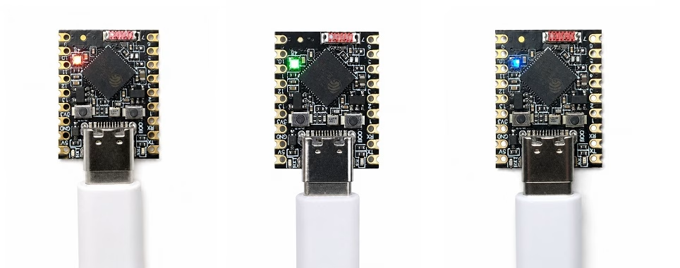
I deliberately limited the color values to 50 instead of the maximum 255. Full-brightness WS2812 LEDs can be surprisingly bright, and there is no reason to run the LED at maximum power for a simple test.
Expected RGB Test Result
The onboard LED should cycle through:
- Red for one second
- Green for one second
- Blue for one second
- Off for one second
What if GPIO48 Does Not Work?
The "Super Mini" name is used by multiple manufacturers, and not all board revisions are identical. Some ESP32-S3 boards use another GPIO for the addressable LED.
If the code runs but the LED remains dark:
- Check the seller's pinout for your exact board.
- Inspect the board for a WS2812-style LED.
- Try the GPIO number specified by the board manufacturer.
- Do not assume that every ESP32-S3 board uses GPIO48.
Testing Wi-Fi
Since the ESP32-S3 includes Wi-Fi, a quick network scan is another useful hardware test. It verifies that the radio and antenna are operating without requiring your Wi-Fi password.
#include <WiFi.h>

void setup() {
  Serial.begin(115200);
  delay(2000);

  WiFi.mode(WIFI_STA);
  WiFi.disconnect();
  delay(100);

  Serial.println("Scanning Wi-Fi networks...");

  int networks = WiFi.scanNetworks();

  if (networks == 0) {
    Serial.println("No Wi-Fi networks found.");
  } else {
    Serial.print(networks);
    Serial.println(" networks found:");

    for (int i = 0; i < networks; i++) {
      Serial.print(i + 1);
      Serial.print(": ");
      Serial.print(WiFi.SSID(i));
      Serial.print(" (");
      Serial.print(WiFi.RSSI(i));
      Serial.println(" dBm)");
    }
  }
}

void loop() {
}
The output will depend entirely on your location. A typical result might look like:
Scanning Wi-Fi networks...
13 networks found:
1: Stacey's_Wifi_2.4 (-65 dBm)
2: Stacey's_Wifi_2.4_EXT (-71 dBm)
3: innengarten_Guest (-82 dBm)
...
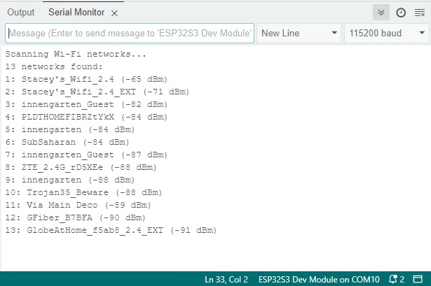
If the board can reliably find nearby 2.4 GHz networks, we now know that the basic radio system and onboard antenna are working.
ESP32-S3 Super Mini BOOT and RESET Buttons
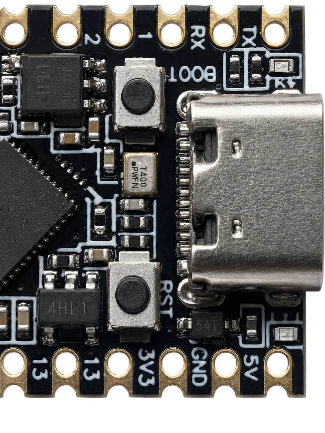
The board normally provides two small buttons: BOOT and RESET.
The RESET button resets the ESP32-S3. The BOOT button is associated with the bootstrapping circuitry and is useful when manually forcing the chip into its firmware download mode.
Most uploads should work without touching either button. However, these buttons become useful if a program crashes early during startup, disables USB functionality or otherwise makes the normal upload process unreliable.
Manually Entering Download Mode
If the Arduino IDE cannot upload to the board, try the following:
- Press and hold BOOT.
- Press and release RESET.
- Release BOOT.
- Check the Arduino IDE's Port menu again.
- Select the newly detected port.
- Upload the sketch.
You can also try holding BOOT while connecting the USB cable.
Troubleshooting the ESP32-S3 Super Mini
No COM Port Appears
First try another USB cable. Some USB-C cables are intended only for charging and contain no data connections.
If the cable is good, manually enter download mode using the BOOT and RESET buttons. Then check whether a new serial device appears.
Sketch Uploads but Serial Monitor is Blank
Verify:
Tools > USB CDC On Boot > EnabledAlso make sure the Serial Monitor baud rate matches the value in:
Serial.begin(115200);After changing USB-related settings, upload the sketch again.
PSRAM Reports 0 Bytes
Check:
Tools > PSRAM > QSPI PSRAMThen rerun the memory test.
If PSRAM is still unavailable, read the ESP32-S3 chip marking. Your board may use a different variant than the common ESP32-S3FH4R2.
Board Resets After Enabling PSRAM
Make sure you did not select OPI PSRAM for an FH4R2 board. Its integrated 2 MB PSRAM uses Quad SPI, so select QSPI PSRAM.
RGB LED Does Not Light
GPIO48 is common for the ESP32-S3 Super Mini RGB LED, but board revisions differ. Verify the pinout supplied with your particular board.
Upload Suddenly Stops Working After Running a Sketch
Because the board uses the ESP32-S3's native USB interface, the USB connection is partly under the control of the microcontroller itself. A crashing application can therefore make the normal serial port disappear.
Use the BOOT/RESET procedure to enter the ESP32-S3 ROM downloader and recover the board.
Uploads Fail at High Speed
If uploads are unreliable, lower the upload speed. A lower setting takes slightly longer but can be more reliable with some computers, USB hubs and cables.
ESP32-S3 Super Mini Test Summary
Before using a generic development board in a larger project, I like to verify its important features instead of relying entirely on the seller's specifications. For the ESP32-S3 Super Mini, the tests in this guide cover most of the board's important hardware.
| Test | Expected Result for Common FH4R2 Board | Actual Result |
|---|---|---|
| CPU identification | ESP32-S3, 2 cores, 240 MHz | ESP32-S3, 2 cores, 240 MHz |
| Flash memory | 4 MB | 4 MB |
| PSRAM detection | 2 MB | 1 MB |
| 1 MB PSRAM allocation | Pass | Pass |
| USB Serial | Pass | Pass |
| RGB LED | Red, green and blue on GPIO48 | Red, green and blue on GPIO48 |
| Wi-Fi scan | Nearby 2.4 GHz networks detected | Pass |
Is the ESP32-S3 Super Mini Worth Using?
The ESP32-S3 Super Mini is an interesting board because it gives you most of the important ESP32-S3 features without the size of a conventional development board.
Compared with smaller single-core ESP32 variants, the S3 gives you considerably more processing power. The common ESP32-S3FH4R2 version also includes 2 MB of PSRAM, which makes it particularly attractive for projects involving displays, large buffers, web interfaces, and other memory-intensive applications.
Native USB is another advantage. Besides normal serial communication, the ESP32-S3's USB hardware makes the chip suitable for projects involving USB devices. That creates possibilities beyond the usual Wi-Fi sensor and web-server projects.
The main disadvantage is documentation. "ESP32-S3 Super Mini" is not one tightly controlled board design, so a pinout or memory specification found online may not describe every version being sold.
Fortunately, we can verify most of the important details ourselves. Check the chip marking, run the flash and PSRAM test, confirm the RGB LED GPIO and keep a copy of the pinout for the exact board you own. Once those details are known, the ESP32-S3 Super Mini becomes a very capable compact development board for embedded and IoT projects.