
This site has built up several tutorials on how to measure almost anything. Now, we add to that list an Arduino pressure sensor featuring the MPS20N0040D and the HX710B Analog-to-Digital IC. By the end, you’ll be able to measure air or liquid pressure and convert it to Pascals, mmHg, or PSI using Arduino.
In a Rush: Wiring the Pressure Sensor to Arduino
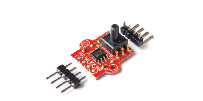
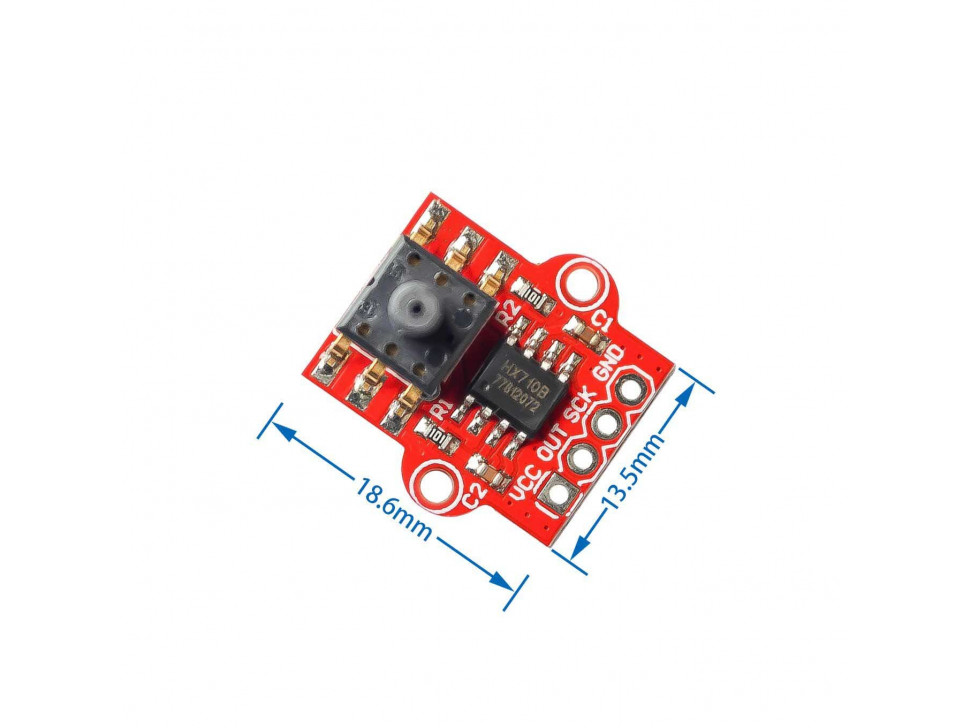
The pressure sensor conveniently sends out pulses according to the pressure data it reads. A clock pin provides timing for that data, like other synchronous protocols. Note that you can use any Arduino digital pin for the clock and data pins. Moreover, the Arduino’s 5V is enough to power the sensor module:
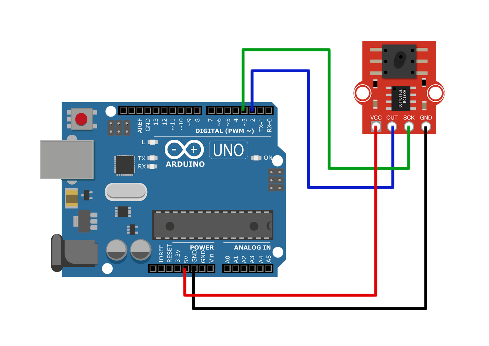
DOUT → D2
SCLK → D3
VCC → 5V
GND → GND
No library specific for this pressure sensor exists but you can use the same HX711 library for weight sensors. The HX711 and HX710B are both 24-bit analog-to-digital converters and provide the same pulse outputs. However, the original HX711 library gives out raw ADC values, not pressure. Hence, I decided to create my library that gives the output in Pascals, mmHg, atm, and psi.
You can clone/download the library on this page and place it directly in the Documents/Arduino/libraries folder.
Here’s an example sketch that displays the pressure in pascals in Serial Monitor:
#include "HX710B.h"

const int DOUT = 2;   //sensor data pin
const int SCLK  = 3;   //sensor clock pin

HX710B pressure_sensor;

void setup() {
  Serial.begin(57600);
  pressure_sensor.begin(DOUT, SCLK);
}

void loop() {

  if (pressure_sensor.is_ready()) {
    Serial.print("Pascal: ");
    Serial.println(pressure_sensor.pascal());
    Serial.print("ATM: ");
    Serial.println(pressure_sensor.atm());
    Serial.print("mmHg: ");
    Serial.println(pressure_sensor.mmHg());
    Serial.print("PSI: ");
    Serial.println(pressure_sensor.psi());
  } else {
    Serial.println("Pressure sensor not found.");
  }

  delay(1000);

}
Want to learn more about how the pressure sensor works? Read on below.
In-Depth: How the MPS20N0040D Pressure Sensor Works
The MPS20N0040D measures the air or liquid pressure in its opening.
Bridge Circuit
The MPS20N0040D pressure sensor is a bridge circuit where one of the bridge elements is a pressure-sensitive resistor. A source voltage is applied to the bridge at points 2 and 5 and output is measured at points 1 or 6, and 4.
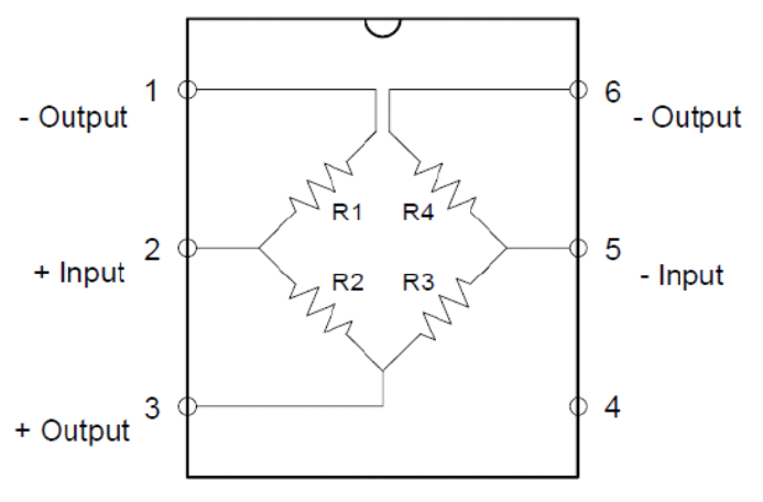
The voltage output at points 1 or 6 and 4 is calculated using this formula:
You’ll notice that when all resistor values are equal, Vout is zero. A bridge with all resistor values equal is known as a balanced bridge.
Let’s say each resistor in the bridge is 10 ohms. Then the voltage output, for a 5V input, is:
When pressure is applied, one of the resistances in the bridge changes value. This unbalances the bridge and Vout is no longer zero.
Let’s say that because of the pressure, R1 changed from 20 ohms to 10 ohms. The value Vout then becomes
A 10-ohm change is a bit generous; in reality, the change in resistance is often very small. This corresponds to the voltage from the sensor Vout also being very small, way below the sensitivity of the Arduino’s ADC. Hence, there’s a need to use an external ADC, with a higher resolution than the Arduino’s 10-bit ADC. That’s the job of the HX710B.
Converting Voltage to Pressure
The HX710B is a 24-bit ADC that sends out pulses based on the voltage it reads. The higher the number of pulses within a specified frame, the higher the voltage measured. A 24-bit ADC can detect a voltage level as low as:
In comparison, a 10-bit ADC, the Arduino’s ADC via the analog input, can detect:
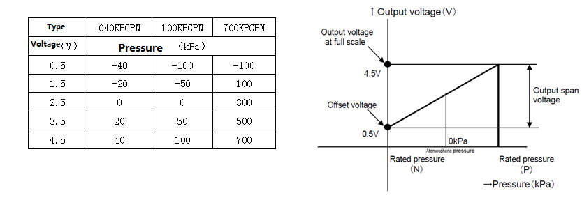
The MPS20N0040D gives out a voltage output that is linearly proportional to the applied pressure in kilopascals.
We can use this formula to convert the ADC output value to pressure in kilopascals.
For a 24-bit ADC like the HX710B, the equation becomes:
This is the equation used in the library to read the pressure in pascals.
For other units of pressure, we just use conversion factors:
Calibrating the MPS20N0040D + HX710B
Factory specs get you close, but a quick two-point calibration (zero + one known pressure) tightens accuracy for your exact tubing, supply, and sensor.
What you’ll do
- Zero the sensor open to atmosphere → record raw ADC value (Raw₀, should map to 0 kPa).
- Apply a known pressure (e.g., 10 kPa from a manometer/syringe gauge) → record raw ADC (Raw₁) and note the actual pressure P₁.
- Compute a linear model:
P=m⋅Raw+bP = m \cdot \text{Raw} + bwherem=P1−0Raw1−Raw0,b=−m⋅Raw0m=\frac{P_1 - 0}{\text{Raw}_1 - \text{Raw}_0},\qquad b= -m \cdot \text{Raw}_0
- Use for conversions (Pa, mmHg, atm, psi).
Tip: Take many samples at each point and average to reduce noise before computing
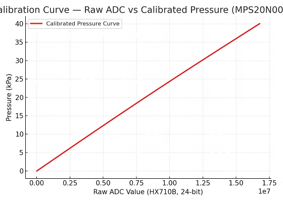
Calibration curve (example)
Example Arduino code (two-point calibration + live reading)
#include "HX710B.h"
#include <EEPROM.h>

const int PIN_DOUT = 2;
const int PIN_SCLK = 3;

// Known reference pressure for second point (kPa)
const double P1_kPa = 10.0;

struct Calib { double m, b; };
HX710B hx;

// Simple EEPROM helpers (store at address 0)
void saveCal(const Calib& c){ EEPROM.put(0, c); }
bool loadCal(Calib& c){
  EEPROM.get(0, c);
  return isfinite(c.m) && isfinite(c.b) && c.m != 0.0;
}

unsigned long avgRaw(uint16_t n=50){
  return hx.readRawAverage(n);
}

void setup(){
  Serial.begin(57600);
  hx.begin(PIN_DOUT, PIN_SCLK);

  Calib c;
  if (loadCal(c)) {
    hx.setCalibration(c.m, c.b);
    Serial.print(F("Loaded calib: m=")); Serial.print(c.m, 10);
    Serial.print(F(", b=")); Serial.println(c.b, 10);
  } else {
    Serial.println(F("No calib found. Press z (zero), then r (ref), then c (compute)."));
  }

  Serial.println(F("Commands: z=zero, r=ref, c=compute-save, p=live print"));
}

unsigned long Raw0=0, Raw1=0;

void loop(){
  if (Serial.available()){
    char cmd = tolower(Serial.read());
    if (cmd=='z'){
      Serial.println(F("[Zero] Keep open to air..."));
      delay(800);
      Raw0 = avgRaw();
      Serial.print(F("Raw0 = ")); Serial.println(Raw0);
    }
    else if (cmd=='r'){
      Serial.print(F("[Ref] Apply known pressure P1_kPa = "));
      Serial.println(P1_kPa, 3);
      delay(800);
      Raw1 = avgRaw();
      Serial.print(F("Raw1 = ")); Serial.println(Raw1);
    }
    else if (cmd=='c'){
      if (Raw1 > Raw0){
        Calib c;
        c.m = (P1_kPa - 0.0) / (double)(Raw1 - Raw0);
        c.b = -c.m * (double)Raw0;
        hx.setCalibration(c.m, c.b);
        saveCal(c);
        Serial.println(F("[Cal] Saved calibration:"));
        Serial.print(F("m=")); Serial.print(c.m, 10);
        Serial.print(F(", b=")); Serial.println(c.b, 10);
      } else {
        Serial.println(F("[Error] Do z then r first."));
      }
    }
    else if (cmd=='p'){
      Serial.println(F("[Live] Calibrated readings (kPa, Pa, psi, mmHg)..."));
      while (!Serial.available()){
        float PkPa = hx.kPaCal();
        float Pa   = PkPa * 1000.0f;
        float psi  = Pa / 6894.757f;
        float mmHg = Pa / 133.322f;
        Serial.print(F("kPa=")); Serial.print(PkPa, 3);
        Serial.print(F("  Pa=")); Serial.print(Pa, 0);
        Serial.print(F("  psi=")); Serial.print(psi, 3);
        Serial.print(F("  mmHg=")); Serial.println(mmHg, 1);
        delay(200);
      }
      while (Serial.available()) Serial.read();
    }
  }
}
How to use
- Open Serial Monitor @ 57600 baud.
- With sensor open to air, press z → records Raw₀.
- Apply the known pressure (e.g., 10 kPa), press r → records Raw₁.
- Press c → computes and saves m and b.
- Press p → live calibrated readings in kPa / Pa / PSI / mmHg.
Good calibration practice
- Average 30–100 samples per point; keep the system still.
- Re-calibrate if you change tube length, liquid density, or supply voltage.
- For liquid level, always zero with the tube tip just at the liquid surface.
- If readings drift, add a 100 nF cap across VCC–GND and try simple moving average filtering.
Optional: keep “factory” fallback
If no EEPROM coefficients are present, you can fallback to a datasheet linear model (e.g., ~1 mV/kPa at 5 V with your ADC conversion). The two-point calibration simply refines that line to your exact setup.
Example Project: Liquid Level Sensor
It is possible for a pressure sensor to measure the current level of any liquid. Here's an example liquid level sensor setup, where the KP610 device can be the MPS20N0040D pressure sensor (image from pressure-sensors.eu):

As the liquid level rises, the pressure inside the tube on the sensor increases. The height of the liquid is proportional to pressure with the formula:
where ρ is the density of the liquid, h is the liquid height and g is the acceleration due to gravity.
Troubleshooting & FAQs
Q: My serial monitor shows “Pressure sensor not found.”
A: Check wiring (DOUT → D2, SCLK → D3). Also confirm the HX710B’s power LED is ON.
Q: The readings jump even with no pressure.
A: Add a 100 nF capacitor across VCC–GND, and average several readings in software.
Q: Can this measure water depth?
A: Yes, use a silicone tube to sense the liquid column. Convert pressure to height with:

For water, (ρ = 1000 kg/m³), (g = 9.81 m/s²).
Q: What’s the safe pressure range?**
A: 0 – 40 kPa (≈ 0 – 0.4 bar). Exceeding this may damage the sensor diaphragm.
Q: Can I use 3.3 V boards (ESP32, Pico)?
A: Yes. The HX710B accepts 2.7 – 5.5 V and uses digital I/O, so it’s logic-level safe.


getting this error while compiling your code with your library
Hx710b:4:11: error: conflicting declaration 'const int SCK'
const int SCK = 3; //sensor clock pin
^
In file included from C:\Program Files (x86)\Arduino\hardware\arduino\avr\cores\arduino/Arduino.h:257:0,
from sketch\Hx710b.ino.cpp:1:
C:\Program Files (x86)\Arduino\hardware\arduino\avr\variants\standard/pins_arduino.h:46:22: note: previous declaration as 'const uint8_t SCK'
static const uint8_t SCK = PIN_SPI_SCK;
^
exit status 1
conflicting declaration 'const int SCK'
me too.
Any update?
Hi Chris and Nouman,
I've updated the source code at the repo. It should be good now. Thanks!
Thanks very much. That problem solved, now a new one:
'class HX710B' has no member named 'begin'
Hmm.. I don't seem to have that problem.. are you using the example sketch from the library?
OK working now incorrect HX710B library added "author=Andhie Setyabudi". Replaced with your now.
please send complete code.