The ESP32-CAM is a compact yet powerful development board that packs Wi-Fi, Bluetooth, and camera capabilities into one low-cost module. But with its limited pin count and dual-purpose GPIOs, figuring out which pins to use can be confusing—especially for beginners. In this post, we’ll break down the ESP32-CAM pinout, explain the function of each pin, and help you avoid common pitfalls when connecting sensors, peripherals, or programming the board.

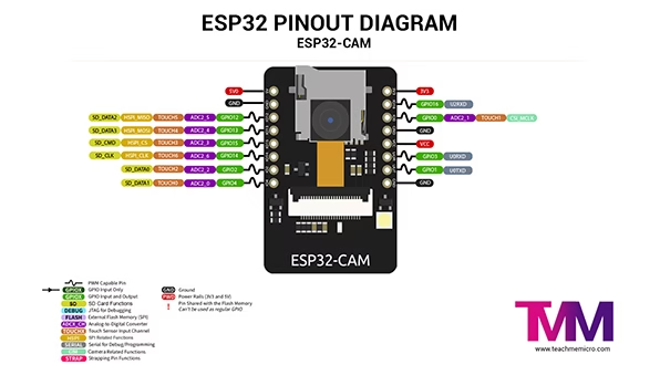
ESP32-CAM Pinout Description
| Pin Name | Description |
|---|---|
| 5V (VCC) | Primary power input (recommended). Often used to power the board from USB/5V supplies. |
| 3V3 (3.3V) | 3.3V output from the regulator. Can power small external sensors (use with caution). |
| GND | Ground (three GND pins available on the board). |
| IO0 (GPIO0) | Boot mode select (pull LOW to enter flash mode). Also used as camera XCLK in some setups — don’t leave it strapped incorrectly. |
| U0T / IO1 (GPIO1) | UART0 TX (serial transmit). Used by the on-board serial console — avoid reassigning during programming. |
| U0R / IO3 (GPIO3) | UART0 RX (serial receive). Used by serial console and required for uploading via UART adapter. |
| IO2 (GPIO2) | Used as SD card DATA0 (also available as general I/O if SD not used). Boot-sensitive on some modules. |
| IO4 (GPIO4) | SD card DATA1 / often tied to the on-board LED — usable if SD/card not in use. |
| IO12 (GPIO12) | SD card DATA2 (also MTDI). Watch this pin’s strapping behavior — avoid if unsure. |
| IO13 (GPIO13) | SD card DATA3 (also MTCK). Commonly used by the microSD interface. |
| IO14 (GPIO14) | SD card CLK (clock line). Usually occupied when using the microSD slot. |
| IO15 (GPIO15) | SD card CMD (command line). Typically used by the onboard microSD card interface. |
| IO16 (GPIO16) | General-purpose I/O (limited availability on some board variants). |
| IO17 (GPIO17) | General-purpose I/O (limited availability on some board variants). |
| GPIO32 (CAM_PWR / PWDN) | Camera power / PWDN control on some board variants (used to enable/disable camera power). |
| microSD slot | Uses many of the above pins (IO2, IO4, IO12–IO15, IO14) — if SD is used those pins aren’t free for other peripherals. |
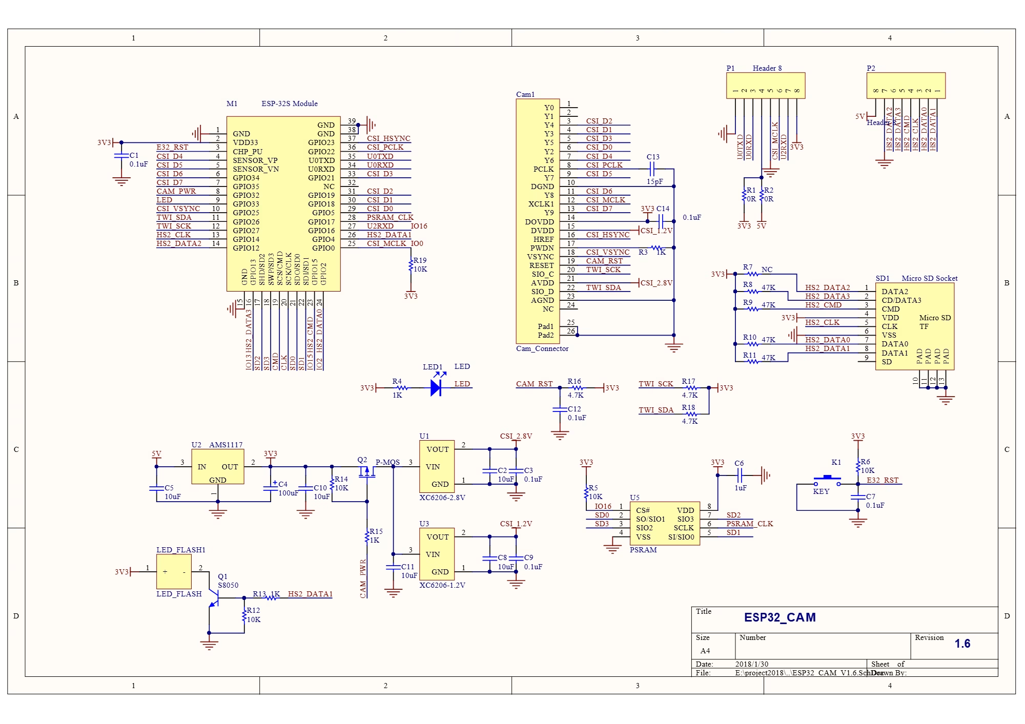
ESP32-CAM Schematic Diagram
The schematic diagram below is a useful reference, together with the pinout, as you make your project.