The “hello world” of microcontroller programming is flashing an LED. As an introduction to Arduino programming, we’ll code several simple Arduino LED sketches; we’ll be blinking an LED, make an LED respond to an input and fade an LED. I’ll also show you how to easily manipulate multiple LEDs and how to use an RGB LED.
Introduction
A microcontroller pin can be an input, output, or floating (undetermined). You must set the pin’s “mode” before you can use it properly. In most microcontrollers, there’s a special register that configures the pins as either of the three states mentioned. We can manipulate those registers directly but Arduino makes it simpler by just calling the pinMode() function.
pinMode(pin number, mode)
The pin number can be any of the digital and analog pins on the Arduino board while the mode can either be INPUT, OUTPUT or INPUT_PULLUP. INPUT and OUTPUT modes are self-explanatory. The INPUT_PULLUP mode activates the pullup resistors inside the Arduino microcontroller. A switch or button is normally connected to a microcontroller pin like this:
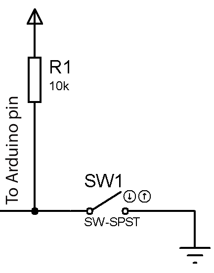
Simply put, if INPUT_PULLUP mode is chosen instead of INPUT, you can now remove the resistor above.
To make a pin high or low, we have the function:
digitalWrite(pin number, state)
Again, the pin number can be any of the digital and analog pins on the board. The state can be HIGH or LOW.
To get the state of a pin that has been set as an input, the function
digitalRead(pin number)
is used. It returns either 1 if the pin state is high or 0 if the pin state is low.
Finally, you can send a series of pulses (PWM) on pins with the ~ sign using the function:
analogWrite(pin number, value)
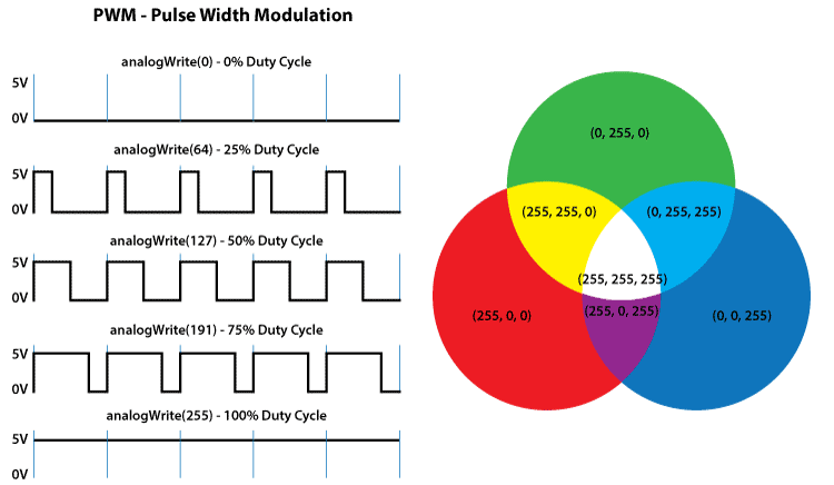
Value can be a number from zero to 255 that represents the duty cycle of the pulses. The duty cycle is the ratio of high pulse over the total pulse. A value of 128 or 50% duty cycle means the high part of the pulse takes half of the total pulse width.
A value of 255 or 100% duty cycle means the total pulse width is all high while a 0 duty cyle means the total pulse width is all low. Later on, we’ll use this concept to vary the power across a LED, adjusting its brightness.
Blinking a LED
Let’s open the most basic Arduino program. Open your Arduino IDE and go to File > Examples > 01.Basics > Blink. This should be the contents of the sketch.
// the setup function runs once when you press reset or power the board
void setup() {
  // initialize digital pin 13 as an output.
  pinMode(LED_BUILTIN, OUTPUT);
}

// the loop function runs over and over again forever
void loop() {
  digitalWrite(LED_BUILTIN, HIGH); // turn the LED on (HIGH is the voltage level)
  delay(1000); // wait for a second
  digitalWrite(LED_BUILTIN, LOW); // turn the LED off by making the voltage LOW
  delay(1000); // wait for a second
}
Here you have your two “bare minimum” functions: setup() and loop(). Setting the mode of the pin is usually done inside the setup() function as seen above.
Most Arduino boards have at least one onboard LEDs whose digital pin is assigned to the constant LED_BUILTIN. For the Arduino UNO, that LED is tied to pin 13.
The blinking part is inside the loop() function. There you see the part where the LED on pin 13 is on and off.
It is necessary to introduce a delay between calls to digitalWrite() so that you can see the blinking. Removing the delay would mean the two digitalWrite() commands will be separated by less than 100 nanoseconds only! Your eyes would not be fast enough to see the LED blinking if that’s the case.
Make a LED Respond to Input
Now let’s modify the program above to respond to an input. You’ll need to wire this circuit:
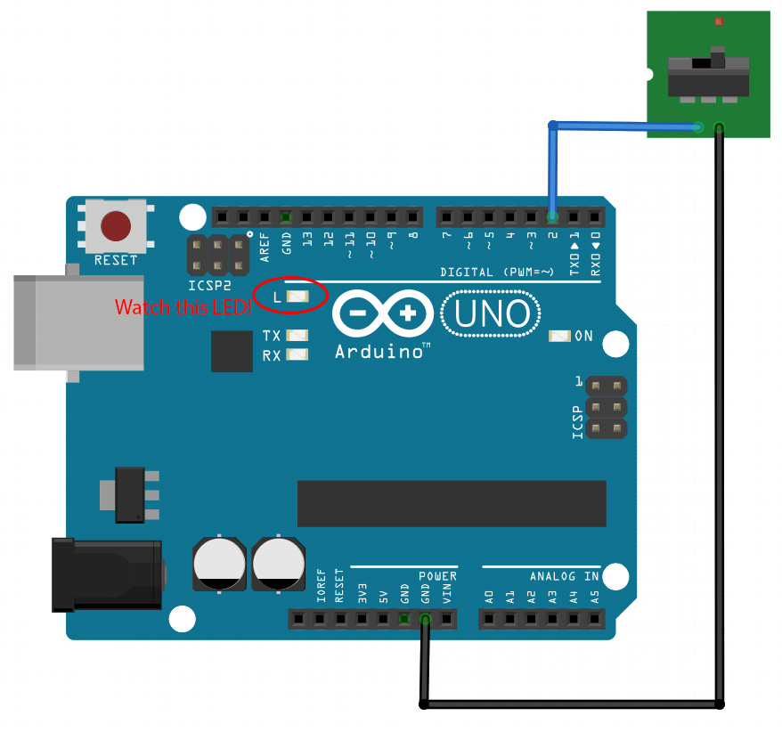
Then load this sketch and save it as “Switch LED “:
// the setup function runs once when you press reset or power the board
void setup() {
  // initialize digital pin 13 as an output and pin 2 as input.
  pinMode(LED_BUILTIN, OUTPUT);
  pinMode(2, INPUT_PULLUP);
}

// the loop function runs over and over again forever
void loop() {
  if(digitalRead(2) == 1){ //check the state of the switch
   digitalWrite(LED_BUILTIN, HIGH); // turn the LED on (HIGH is the voltage level)
  else{
   digitalWrite(LED_BUILTIN, LOW); // turn the LED off by making the voltage LOW
  }
}
Here we placed the digitalRead() function inside an if condition. If the state of the switch on pin 2 is high (1) then pin 13 is also high. Otherwise, pin 13 is low.
Fading a LED
As mentioned above, we can use the analogWrite() function to control the power across a LED and vary its brightness. This is based from the formula:
So if a LED is receiving pulses at 50% duty cycle then it is receiving only half of the voltage supplied. For the Arduino whose pins operate at 5V, this means 2.5V.
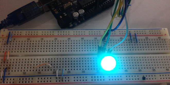
We can't fade the on-board LED so we need to wire this circuit:
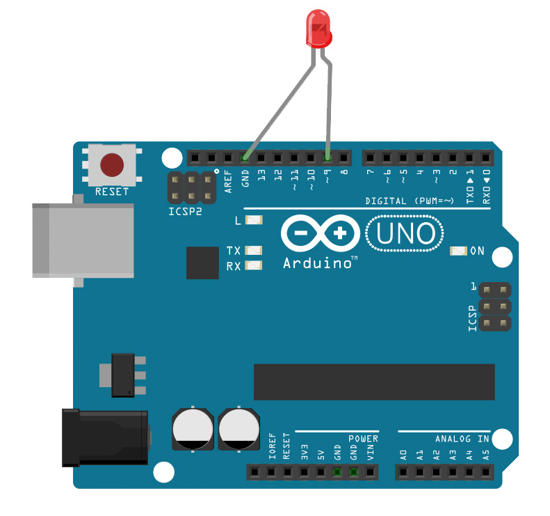
And load the sketch at File > Examples > 01.Basics > Fade:
int led = 9;           // the pin that the LED is attached to
int brightness = 0;    // how bright the LED is
int fadeAmount = 5;    // how many points to fade the LED by

// the setup routine runs once when you press reset:
void setup() {
  // declare pin 9 to be an output:
  pinMode(led, OUTPUT);
}

// the loop routine runs over and over again forever:
void loop() {
  // set the brightness of pin 9:
  analogWrite(led, brightness);

  // change the brightness for next time through the loop:
  brightness = brightness + fadeAmount;

  // reverse the direction of the fading at the ends of the fade:
  if (brightness == 0 || brightness == 255) {
    fadeAmount = -fadeAmount ;
  }
  // wait for 30 milliseconds to see the dimming effect
  delay(30);
}
to see the LED fade in and out!
Multiple Simultaneous LEDs
The special register I mentioned used to control the pin direction is named DDR or Data Direction Register. But before I go on, you must know the pinout of the ATMega328p which is the microcontroller inside the Arduino UNO:
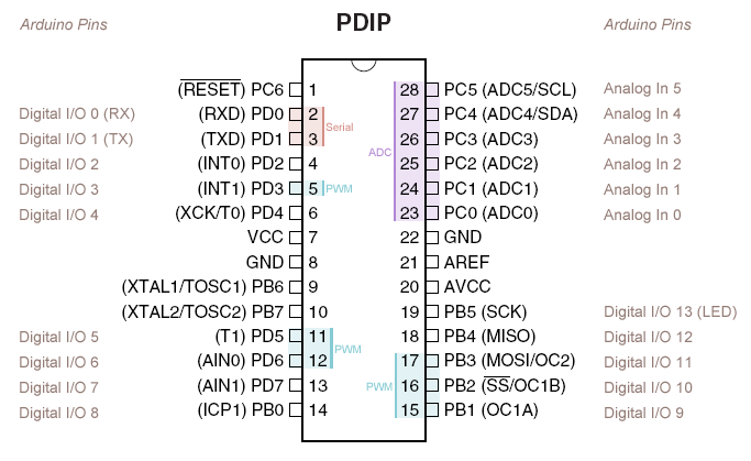
On the extremes, you see the corresponding Arduino UNO pin names of each pin. The I/O pins are grouped in three ports: PORTB, PORTC and PORTD. Moreover, each group has their own data direction registers: DDRB, DDRC and DDRD. They also have separate registers for reading the pin states: PINB, PINC and PIND.
Using the DDR Registers
Now, to set the direction of the pin, you need to modify the corresponding DDR register. For example, setting all PORTB as output would require all DDRB bits to be high:
DDRB = B11111111
Conversely, setting all PORTB as output requires clearing all DDRB bits:
DDRB = B00000000
The code below blinks all PORTB pins or digital 8 to 13 pins:
void setup(){
  DDRB =  B00011111;
}

void loop(){
  PORTB = B00011111;
  delay(1000);
  PORTB = B00000000;
  delay(1000);
}
The code above is certainly much shorter than doing this:
void setup(){
 pinMode(8, OUTPUT);
 pinMode(9, OUTPUT);
 pinMode(10, OUTPUT);
 pinMode(11, OUTPUT);
 pinMode(12, OUTPUT);
 pinMode(13, OUTPUT);
}

void loop(){
 digitalWrite(8, HIGH);
 digitalWrite(9, HIGH);
 digitalWrite(10, HIGH);
 digitalWrite(11, HIGH);
 digitalWrite(12, HIGH);
 digitalWrite(13, HIGH);
 delay(1000);
 digitalWrite(8, LOW);
 digitalWrite(9, LOW);
 digitalWrite(10, LOW);
 digitalWrite(11, LOW);
 digitalWrite(12, LOW);
 digitalWrite(13, LOW);
 delay(1000);
}
Arduino Seven Segment Displays
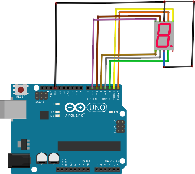
Doing direct port manipulation is also useful when using seven segment displays. Let’s say you want to display the digit “5” and used this wiring diagram:
To display “5”, the segments a, c, d, f and g should light up:
That means digital pins 0, 2, 3, 5 and 6 should be high while the rest are low. The code would be:
void setup(){
   DDRD = B11111111;
}

void loop(){
  PORTD = B01101101;
}
An article on Arduino simultaneous pin manipulation shows how to do the rest of the digits and count them up or down.
Arduino RGB LED
An RGB LED is a LED with four pins: one for red, green and blue and for the common cathode. There are six-pin variants which means each color has their own cathode. An RGB LED is essentially three LEDs merged into one which you can use to create different colors according to the RGB spectrum.
How RGB LEDs Work
Different colors are produced depending on the magnitude of the three basic colors. Moreover, the magnitude is based on the duty cycle of the PWM signal applied to each pin.
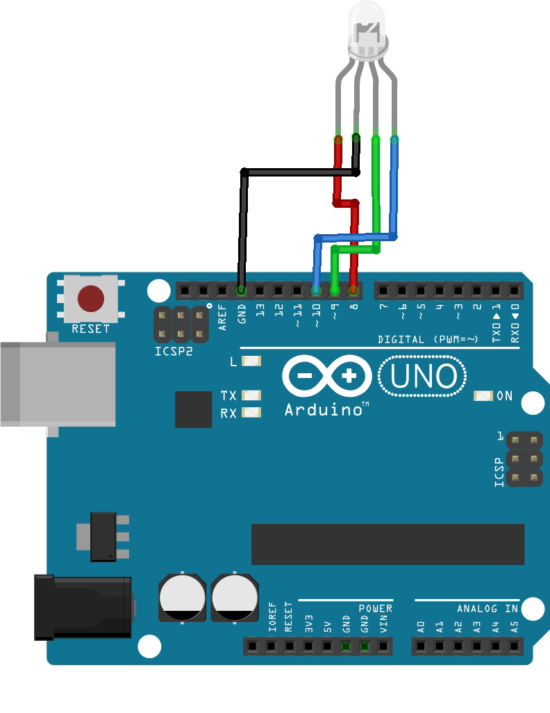
As discussed above, PWM signals are produced using the analogWrite() function. Let’s say an RGB LED is connected to digital pins 8, 9 and 10 like so:
For example, to produce a color red, you need to max out the duty cycle for the red pin and 0 for the rest:
analogWrite(255, redPin)
analogWrite(0, greenPin)
analogWrite(0, bluePin)
The color yellow is produced using full values for red and green:
analogWrite(255, redPin)
analogWrite(255, greenPin)
analogWrite(0, bluePin)
Moreover, we can create a simple function that sets the RGB LED’s color:
void setColor(int red, int green, int blue){
        analogWrite(red, redPin)
        analogWrite(green, greenPin)
        analogWrite(blue, bluePin)
}
Finally, here’s the sketch that uses the function above, displaying all colors of the rainbow sequentially:
int redPin = 8;
int greenPin = 9;
int bluePin = 10;

void setup(){
        pinMode(redPin, OUTPUT);
        pinMode(greenPin, OUTPUT);
        pinMode(bluePin, OUTPUT);
}

void loop(){
        setColor(255, 0, 0); //red
        delay(500);
        setColor(255,165,0); //orange
        delay(500);
        setColor(255, 255, 0); //yellow
        delay(500);
        setColor(0, 255, 0); //green
        delay(500);
        setColor(0, 0, 255); //blue
        delay(500);
        setColor(138,43,226); //violet
        delay(500);
}

void setColor(int red, int green, int blue){
        analogWrite(red, redPin);
        analogWrite(green, greenPin);
        analogWrite(blue, bluePin);
}
Check out my separate tutorial on Arduino RGB LEDs for more!