
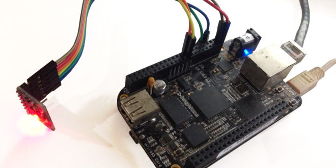
I2C is a popular communications protocol and is used by a lot of sensors and devices. This is why most microcontrollers, including Arduino, PICs, and STM32 have I2C support. In this tutorial, we will look at how to use the I2C protocol on the BBB and create a simple Beaglebone Black I2C application.
Beaglebone Black I2C Bus
There are three I2C buses on the Beaglebone Black according to the AM335X Technical Reference Manual and their memory addresses are:
- i2c-0: 0x44E0_B000
- i2c-1: 0x4802_A000
- i2c-2: 0x4819_C000
The i2c-0 bus is not accessible on the header pins while the i2c-1 bus is utilized for reading EEPROMS on cape add-on boards and may interfere with that function when used for other digital I/O operations.
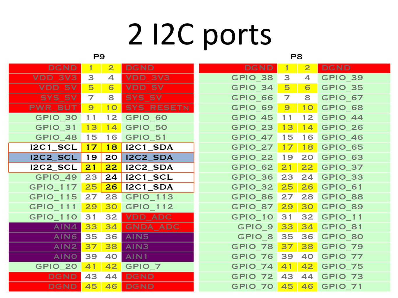
The i2c-2 bus is the one that is free for use so we'll be using that in this tutorial.
Linux I2C Tools
Thankfully, Linux has built-in i2c tools that make our lives easier (unlike with BBB PWM). To check which of the three buses are enabled we can use i2cdetect:
root@arm:~# i2cdetect -l
i2c-0   i2c             OMAP I2C adapter                        I2C adapter
i2c-2   i2c             OMAP I2C adapter                        I2C adapter
Mine's showing two i2c devices. But again we can't use i2c-0 so we'll go with i2c-2.
To detect the devices connected to i2c-2:
root@arm:~# i2cdetect -r 2
WARNING! This program can confuse your I2C bus, cause data loss and worse!
I will probe file /dev/i2c-2 using read byte commands.
I will probe address range 0x03-0x77.
Continue? [Y/n] y
     0  1  2  3  4  5  6  7  8  9  a  b  c  d  e  f
00:          -- -- -- -- -- -- -- -- -- -- -- -- --
10: -- -- -- -- -- -- -- -- -- -- -- -- -- -- -- --
20: -- -- -- -- -- -- -- -- -- -- -- -- -- -- -- --
30: -- -- -- -- -- -- -- -- -- -- -- -- -- -- -- --
40: -- -- -- -- -- -- -- -- -- -- -- -- -- -- -- --
50: -- -- -- -- UU UU UU UU -- -- -- -- -- -- -- --
60: -- -- -- -- -- -- -- -- 68 -- -- -- -- -- -- --
70: -- -- -- -- -- -- -- --
root@arm:~#
Those addresses with UU are reserved addresses. Noticed there is a 68. That's because I connected a device with an I2C address of 68 to my Beaglebone Black.
Writing and Reading from the I2C Bus
Now, to write to the I2C bus, we can use:
i2cset -y 2 0x68 0xf4 0x34
The first hex number is the I2C device address followed by the specific data address and the byte to be written. You can read more about the i2cset at https://linux.die.net/man/8/i2cset.
To read the registers from the device connected to the I2C bus, the i2cdump command can be used:
root@arm:~# i2cdump -y 2 0x68 w
     0,8  1,9  2,a  3,b  4,c  5,d  6,e  7,f
00: 01ff ff01 2dff af2d 0faf 050f 9005 fb90
08: 0bfb 050b 4405 2844 7028 6e70 946e c694
10: 00c6 0000 0000 0000 0000 0000 0000 0000
18: 0000 0000 0000 0000 0000 0000 0000 0000
20: 0000 0000 0000 0000 0000 0000 0000 0000
28: 0000 0000 0000 0000 0000 0000 0000 0000
30: 0000 0000 0000 0000 0000 0000 0000 0000
38: 0000 0100 cd01 54cd 25e8 9825 04cc 4804
40: f454 70f4 ff50 d4ff 01de ca01 00be 8800
48: 0078 0000 0000 0000 0000 0000 0000 0000
50: 0000 0000 0000 0000 0000 0000 0000 0000
58: 0000 0000 0000 0000 0000 0000 0000 0000
60: 0000 0000 0000 0000 0000 0000 0000 0000
68: 0000 0000 0000 0000 0000 3000 2031 1307
70: 0000 0000 0000 0000 0000 0068 0000 0000
78: 0000 0000 0000 0000 0000 0000 0000 ff00
80: 01ff ff01 2dff af2d 0faf 050f 9005 fb90
88: 0bfb 050b 4405 2844 7028 6e70 946e c694
90: 00c6 0000 0000 0000 0000 0000 0000 0000
98: 0000 0000 0000 0000 0000 0000 0000 0000
a0: 0000 0000 0000 0000 0000 0000 0000 0000
a8: 0000 0000 0000 0000 0000 0000 0000 0000
b0: 0000 0000 0000 0000 0000 0000 0000 0000
b8: 0000 0100 cd01 00ce 2400 6824 04bc 9c04
c0: f4e8 70f4 ff50 bcff 01ae 7201 0072 8500
c8: 0084 0000 0000 0000 0000 0000 0000 0000
d0: 0000 0000 0000 0000 0000 0000 0000 0000
d8: 0000 0000 0000 0000 0000 0000 0000 0000
e0: 0000 0000 0000 0000 0000 0000 0000 0000
e8: 0000 0000 0000 0000 0000 3600 2137 a020
f0: 0000 0000 0000 0000 0000 0068 0000 0000
f8: 0000 0000 0000 0000 0000 0000 0000 ff00
Read more about i2cdump here: https://linux.die.net/man/8/i2cdump
Finally, we can acquire the data from a specific register on the I2C device using i2cget:
root@arm:~# i2cget -y 2 0x68 0x87
0xff
Here's more information for i2cget: https://linux.die.net/man/8/i2cget.
In the next part of this tutorial, we'll be reading data from the MPU6050 gyroscope + accelerometer and displaying it on the Beaglebone Black terminal. Follow this blog for updates!


Hi,
I am facing one problem while doing i2cset and i2cget.But in different board.
I am using AMD MF bettong DDR4 board.
kernel version is : 4.4.11-158-amd+
I am doing i2cset works fine.
But i2cget reads 0xff all the time.
commands used is:
sudo i2cset -y 6 0x50 0x6c 00
sudo i2cget -y 6 0x50 0x6c
i2cdump also reads 0xff all the time irrespective of the value written!!!
cae@cae-Bettong:~$ sudo i2cdump 6 0x50
No size specified (using byte-data access)
WARNING! This program can confuse your I2C bus, cause data loss and worse!
I will probe file /dev/i2c-6, address 0x50, mode byte
Continue? [Y/n] y
0 1 2 3 4 5 6 7 8 9 a b c d e f 0123456789abcdef
00: ff ff ff ff ff ff ff ff ff ff ff ff ff ff ff ff ................
10: ff ff ff ff ff ff ff ff ff ff ff ff ff ff ff ff ................
20: ff ff ff ff ff ff ff ff ff ff ff ff ff ff ff ff ................
30: ff ff ff ff ff ff ff ff ff ff ff ff ff ff ff ff ................
40: ff ff ff ff ff ff ff ff ff ff ff ff ff ff ff ff ................
50: ff ff ff ff ff ff ff ff ff ff ff ff ff ff ff ff ................
60: ff ff ff ff ff ff ff ff ff ff ff ff ff ff ff ff ................
70: ff ff ff ff ff ff ff ff ff ff ff ff ff ff ff ff ................
80: ff ff ff ff ff ff ff ff ff ff ff ff ff ff ff ff ................
90: ff ff ff ff ff ff ff ff ff ff ff ff ff ff ff ff ................
a0: ff ff ff ff ff ff ff ff ff ff ff ff ff ff ff ff ................
b0: ff ff ff ff ff ff ff ff ff ff ff ff ff ff ff ff ................
c0: ff ff ff ff ff ff ff ff ff ff ff ff ff ff ff ff ................
d0: ff ff ff ff ff ff ff ff ff ff ff ff ff ff ff ff ................
e0: ff ff ff ff ff ff ff ff ff ff ff ff ff ff ff ff ................
f0: ff ff ff ff ff ff ff ff ff ff ff ff ff ff ff ff ................
cae@cae-Bettong:~$
Please let me know why i am not able to write to EEPROM?
I am using one i2c test application to receive i2c 1 or 2 bytes.After running which only i2c slave will be attached to i2c bus!
And also running the application changes the register values,which is read using printk() in the driver.
That time also i2cdump or i2cget reads 0xff !!!!
Why is this happening?? can anyone please let me know?
Thanks & Regards,
Kripashree
Hello
You're device and board is quite different to what I'm presenting here but normally, a 0xFF reading indicate a timing mismatch between the master and the slave device. Maybe there is something wrong with the wiring because one reason for mismatches are voltage spikes or not reaching voltage thresholds for both low and high pulses.
hello, im trying to scan the registry of for i2c address ("KSZ9897R" 7-Port Gigabit Ethernet Switch with Two RGMII/MII/RMII Interfaces) , on the schematic it's writing that the address is :0xBE which i didnt find it, and there is another address for the poe+ which is: 0x20 i already found it.
i use this commande i2cdetect -r 2 and its ok, but the issue that the range of this commande is " 0x03-0x77."
and the address that im looking for is 0xBE, which is obviously outside of this range, what i can do to have a bigger range to scan so i can catch the address im looking for.
thx you
debian@beaglebone:~$ i2cdetect -r 2
WARNING! This program can confuse your I2C bus, cause data loss and worse!
I will probe file /dev/i2c-2 using read byte commands.
I will probe address range 0x03-0x77.
Continue? [Y/n] y
0 1 2 3 4 5 6 7 8 9 a b c d e f
00: -- -- -- -- -- -- -- -- -- -- -- -- --
10: -- -- -- -- -- -- -- -- -- -- -- -- -- -- -- --
20: 20 -- -- -- -- -- -- -- -- -- -- -- -- -- -- --
30: 30 -- -- -- -- -- -- -- -- -- -- -- -- -- -- --
40: -- -- -- -- -- -- -- -- -- -- -- -- -- -- -- --
50: 50 -- -- -- UU UU UU UU -- -- -- -- -- -- -- --
60: -- -- -- -- -- -- -- -- -- -- -- -- -- -- -- --
70: -- -- -- -- -- -- -- --
hello. how i can enlarge the rang in the beagle bone to scan the registry from 0x03-0x77, to more than that till i reach the address 0xBE, because the address i'm searching for is 0xBE it's for an Ethernet switch "KSZ9897R"
Hello Mahmoud,
You can specify the first and last address of i2cget using this command:
i2cdetect -r 2 0x00 0xBE
This scans from 0x00 to 0xBE.
hello,, thx for your reply, i tried this command but it seems that the beaglebone doesnt support this range, it says out of rang, this is the result of the commande
Last login: Mon Feb 5 15:33:33 UTC 2018 on ttyGS0
Linux beaglebone 4.4.9-ti-r25 #1 SMP Thu May 5 23:08:13 UTC 2016 armv7l
The programs included with the Debian GNU/Linux system are free software;
the exact distribution terms for each program are described in the
individual files in /usr/share/doc/*/copyright.
Debian GNU/Linux comes with ABSOLUTELY NO WARRANTY, to the extent
permitted by applicable law.
debian@beaglebone:~$ i2cdetect -r 2 0x00 0xBE
Error: FIRST argument out of range (0x03-0x77)!
Usage: i2cdetect [-y] [-a] [-q|-r] I2CBUS [FIRST LAST]
i2cdetect -F I2CBUS
i2cdetect -l
I2CBUS is an integer or an I2C bus name
If provided, FIRST and LAST limit the probing range.
debian@beaglebone:~$
Ah yes, it is expected. Sorry I thought you are using a device other than BBB. 0x77 is the maximum address because addresses beyond that are used for 10-bit I2C mode. Also, I don't think the address of your device is 0xBE. You must convert it to 7-bit by dropping the 7th bit and OR'ing the 0th bit to the write/flag bit (which is done automatically by the kernel, btw). So 0xBE should be 0x5F which is within range.
0xBE = 101111100
remove 0th bit and shift bits to the right
01011111 = 0x5F
you can now read the data from your device using:
i2cdetect -r 2 0x03 0x5F
I hope this answers your problem
What a great tutorial.
Did you have to pull up the I2C connection to be able to detect the device?
I used MPU6050 for this example so there was no need for a pull-up resistor
Thanks for that Roland, It seems as though my device isn't being picked up with i2cdetect and I was suspecting that it would require a pull up resistor but unsure at this stage. What would you do to test that?
Hi Yasir
May I know what device you are using?
Hi Roland,
I seem to have got the address successfully.
I am driving an LED array using an ISSI IS31FL3741 LED driver which is apart of their Evaluation Board. I am trying to hook up the BeagleBone to be able to send i2c commands to the uC onboard the evaluation board and toggle the LED's.
Hi Roland,
It still seems confusing as to how one can write a program to write to an I2C slave device and control. Command line is great but writing a script that could be run and looped is something that I am still looking into. Any advice?
Hi Yasir,
You can always use shell scripts to run bash commands like i2cget, i2cset, etc. I assume you are not familiar with this so let me share a bit.
A typical script contains these:
#!/bin/bash
command1
sudo command2
command3
sudo command4
this is normally a .sh file that you can make executable using
chmod +x script.sh
to run it:
./script.sh
you can also use conditional statements, loops, etc in shell scripts. I would recommend this site: https://www.shellscript.sh/
Thanks for that Roland, I was not aware of that possibility and will start experimenting with it immediately.
How would you set the clock frequency with those commands? Since the slave would only operate at either 400kHz or 1Mhz. I assume real-time communication is not possible with this method on the BBB?
For changing speeds, you have to update the I2C device tree overlay of the BBB. I have written articles about device tree overlays here.
For real-time communication, you can use the BBB's PRU (programmable real-time unit) which is like a separate microcontroller. Using it isn't easy though and I haven't tried using it with I2C. Maybe I'll write about that in the future.
PRU's are definitly what caught my attention when selecting the beaglebone for their realtime capabilities and potential of using processor heavy tasks with linux to control the PRUSS is really promising. I hope it gets clearer as to how one could tap into the PRUSS as it does not seem to be similar to programming an AVR microcontroller at all.
hello, thank you for answering me, im using beagle bean green, does that make any difference?
i tried what you've told me to do, but it didnt work too.
Debian GNU/Linux comes with ABSOLUTELY NO WARRANTY, to the extent
permitted by applicable law.
debian@beaglebone:~$ i2cdetect -r 2 0x03 0x5F
WARNING! This program can confuse your I2C bus, cause data loss and worse!
I will probe file /dev/i2c-2 using read byte commands.
I will probe address range 0x03-0x5f.
Continue? [Y/n]
0 1 2 3 4 5 6 7 8 9 a b c d e f
00: -- -- -- -- -- -- -- -- -- 0c -- -- --
10: -- -- -- -- -- -- -- -- -- -- -- -- -- -- -- --
20: 20 -- -- -- -- -- -- -- -- -- -- -- -- -- -- --
30: 30 -- -- -- -- -- -- -- -- -- -- -- -- -- -- --
40: -- -- -- -- -- -- -- -- -- -- -- -- -- -- -- --
50: 50 -- -- -- UU UU UU UU -- -- -- -- -- -- -- --
60:
70:
debian@beaglebone:~$ i2cdetect -r 2 0x03 0x5F
WARNING! This program can confuse your I2C bus, cause data loss and worse!
I will probe file /dev/i2c-2 using read byte commands.
I will probe address range 0x03-0x5f.
Continue? [Y/n]
0 1 2 3 4 5 6 7 8 9 a b c d e f
00: -- -- -- -- -- -- -- -- -- -- -- -- --
10: -- -- -- -- -- -- -- -- -- -- -- -- -- -- -- --
20: 20 -- -- -- -- -- -- -- -- -- -- -- -- -- -- --
30: 30 -- -- -- -- -- -- -- -- -- -- -- -- -- -- --
40: -- -- -- -- -- -- -- -- -- -- -- -- -- -- -- --
50: 50 -- -- -- UU UU UU UU -- -- -- -- -- -- -- --
60:
70:
about the address of the ship as u said i found this in the datasheet of the device:
The management interface may be configured to be an I2C slave. In this mode, an I2C master has complete programming
access to the device's internal control and status registers, including all MIB counters, address lookup tables,
VLAN table and ACL table.
The 7-bit device address is fixed as 1011_111. Because of the fixed address, only one KSZ9897R may be on the I2C
bus at a time. The R/W control bit is then appended as the least significant bit to form these 8-bit address/control words:
1011_1110
1011_1111
Hello Mahmoud,'
Yes, it confirms that 0x5F is indeed the I2c address of that device and not 0xBE. I2C specifications states that there is only 7-bit or 10-bit addresses.
There is a reason why the I2C address range is 0x03 to 0x77. For 7-bit addressing, you have 128 possible numbers, (0-127 or 0x00 to 0x7F). Out of those 128, there are 8 reserved addresses:
000 0000 0 General call address
000 0000 1 START byte
000 0001 X CBUS address
000 0010 X Reserved for different bus format
000 0011 X Reserved for future purposes
000 01XX X Hs-mode master code
111 10XX X 10-bit slave addressing
111 11XX X Reserved for future purposes
Thus, the valid i2c address for devices is from 0x03 (CBUS 0x11 is allowed) to 0x77 (0x78 to 0x7F are used for 10-bit addressing or "Reserved for future purposes" above).
So I think the i2cdetect command I just gave might be correct but there are other problems involved. Did you follow this diagram for wiring the device with your Beaglebone Green?
hello Roland,
i have an evaluation board for this ship ( EVB-KSZ9897) i run the i2cdetect command and it gives me the address 0x5f.
on my board i have some different values for the resistors like 1k ohms for both scla and sda, and for the led3_1 i tested on the oscilloscope it give logic output 1 but i put already 10k to the vddio, and the led4-1 the resistor was 220 ohms i changed to 1k, than i ran the order again but nothing happen always the same result as before.
hello Rolland,
thx for you help, i found the problem last week, it was a crystal issue, but now i have another issue that the internet is intermittent when i want to use it as PoE, but when i use the data only it's good, im investigating about that, thx for your help 🙂
Glad to hear you were able to solve it Mahmoud. I hope you solve the other problem as well.
can anyone post c++ code for i2c. i am working with battery fuel gauge. my c++ does not work on it.
I built a system around a BeagleBone Black Rev some time ago with the I2C bus connected to Pins P9-19 (SCL) and P9-20 (SDA). I have three or four prototypes configured that way, they all work fine and and I have not touched the I2C code for quite some time.
I recently bought another BeagleBone Black Rev C from Mouser and it was manufactured by GHI. I plugged it into an existing system and installed the SD memory from a functioning system into it and could not see any activity on the I2C bus, nothing. I Swapped it with the BBB originally in the system and that BBB worked fine. I swapped again and the new one still would not communicate over the I2C bus. I tried the new one on two other systems with the same results. I contacted GHI and the sent a replacement. It doesn't work either. Everything on these two new BBB Rev C works fine except this bus.
Since the memory os POP right on top the processor I can't tell it the processor is the same between the old BBB and the new BBB. I suspect that TI may have rev'ed the silicon and this bus is no longer available on these pins.
Any one have any idea what is going on here.
thanks,
john
Aim: Work with three I2C Slave devices.
All three devices have the same address 0x29. so differentiate slave device address need different i2c address. How to set Slave Device Address in BeagleBone Black.
Trying to work with i2c device and i2c-tools on beaglebone.
Need to issue general call reset according NXP's I2C documentation (UM10204) which I understand is at address 0x00 with value 0x06.
Didn't work for me with i2cset -y -a 2 0x00 0x06
Is there a hint how to apply general reset with i2c-tools?
Thanks a lot