
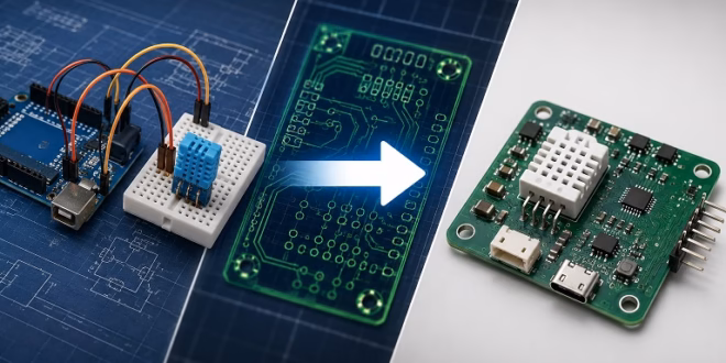
Many Arduino projects start on a breadboard, but a working prototype is not the same as a reliable finished product. If you want to turn an Arduino sensor circuit into something you can install, sell, or duplicate, the next step is designing a PCB and preparing it for turnkey PCB assembly. This means converting your breadboard circuit into proper design files that can be used for PCB fabrication, component sourcing, and assembly.
In this article, we will walk through the process of turning a simple Arduino sensor project into a manufactured PCB. As an example, we will use an Arduino-based temperature, humidity, and pressure sensor project using the BME280 sensor. The same process also applies to many other Arduino sensor projects, such as soil moisture monitors, light sensors, gas sensors, data loggers, and weather stations.
Start with a Working Arduino Prototype
Before designing a PCB, make sure your circuit already works on a breadboard or prototype board. PCB design should not be the first step. It is much easier to troubleshoot a circuit while it is still built using jumper wires and modules.
For example, a basic Arduino BME280 project may include:
- An Arduino Uno, Nano, or Pro Mini
- A BME280 sensor module
- Jumper wires
- A breadboard
- A USB cable or external power supply
- A working Arduino sketch
- Serial Monitor output showing valid sensor readings
At this stage, your goal is to prove that the circuit and code work together. Check that the sensor responds correctly, the I2C address is correct, and the readings are stable.
A typical BME280 module uses I2C communication. That means it needs four basic connections:
| BME280 Pin | Arduino Uno/Nano Pin |
|---|---|
| VCC | 3.3V or 5V, depending on module |
| GND | GND |
| SDA | A4 |
| SCL | A5 |
Some BME280 modules already include voltage regulation and pull-up resistors. Others are bare 3.3V sensor breakout boards. Before turning the circuit into a PCB, always check the exact module or sensor chip you are using.
Draw the Actual Schematic
A breadboard circuit is only a temporary physical layout. A PCB starts with a schematic.
The schematic is the electrical map of your circuit. It shows how every component connects to every other component. Even if your breadboard looks simple, you should redraw the full circuit properly before making the PCB.
For an Arduino sensor PCB, your schematic may include:
- Microcontroller or Arduino module
- BME280 sensor or sensor module
- Power input connector
- Voltage regulator
- Decoupling capacitors
- Pull-up resistors for I2C
- Reset circuit
- Programming header
- Status LED
- Optional display or output connector
Do not simply copy the breadboard wiring without thinking. Breadboard prototypes often use ready-made modules that hide important details such as regulators, pull-up resistors, and level-shifting circuits. When making your own PCB, you need to decide whether those parts will still be included.
Choose Between an Arduino Module and a Bare Microcontroller
One of the most important decisions is whether your PCB will use a complete Arduino module or just the microcontroller.
For beginners, using an Arduino Nano or Pro Mini footprint on the PCB is usually the easiest approach. Instead of placing the ATmega328P and all of its support components directly on your board, you can plug in a small Arduino module.
| Approach | Advantages | Disadvantages |
| Arduino Nano footprint | Easy to design, easy to replace, USB already included | Larger and less professional-looking |
| Arduino Pro Mini footprint | Smaller than Nano, simple design | Needs USB-to-serial adapter for programming |
| Bare ATmega328P | More compact and lower cost at quantity | Needs clock, reset, bootloader, programming header, and careful design |
| ESP32 or other MCU | More powerful, can add Wi-Fi/Bluetooth | More power and boot-pin considerations |
If this is your first manufactured PCB, using an Arduino Nano footprint is a practical choice. It reduces the number of things that can go wrong. Once you are comfortable with PCB design, you can move to a bare microcontroller design.
Replace Breadboard Parts with PCB Footprints
In PCB design software, every component needs two things:
- A schematic symbol
- A PCB footprint
The symbol is used in the schematic. The footprint is the actual physical pad layout on the PCB.
This is where many beginner PCB mistakes happen. A circuit may be electrically correct but still fail because the footprint is wrong.
For example:
- A connector may be mirrored.
- A resistor package may be too small to solder by hand.
- A sensor module header may have the wrong pin spacing.
- A voltage regulator may use a different pin order.
- A capacitor footprint may not match the part you ordered.
Before sending your board for manufacturing, print the PCB layout at 1:1 scale and place the actual parts on top of the paper. This simple check can catch many footprint problems before they become expensive.
Plan the Power Supply
Breadboard prototypes are often powered from the Arduino USB port. A manufactured PCB may need a more permanent power solution.
Ask these questions before finalizing the design:
- Will the board be powered by USB?
- Will it use a 5V adapter?
- Will it use a battery?
- Does the sensor require 3.3V?
- Does the microcontroller require 5V or 3.3V?
- How much current does the entire circuit need?
- Do you need reverse-polarity protection?
- Do you need a power switch?
For a BME280 project, power is especially important because the actual BME280 sensor chip is a 3.3V device. Many breakout modules include a regulator and can accept 5V, but the bare sensor chip should not be connected directly to 5V.
A good PCB design should include decoupling capacitors near the power pins of important components. A common value is 0.1 uF for local decoupling, often paired with a larger capacitor such as 10 uF near the power input or regulator output.
Add Pull-Up Resistors for I2C
The BME280 commonly uses I2C, which requires pull-up resistors on the SDA and SCL lines. Many sensor modules already include these resistors, but if you are placing the sensor directly on your PCB, you may need to add them yourself.
Typical I2C pull-up resistor values are 4.7 kOhms or 10 kOhms, depending on bus speed, voltage, and wiring length.
For short PCB traces, 4.7 kOhms is commonly used. If multiple modules already have pull-up resistors, the effective resistance may become too low. This is another reason why you should understand whether you are using a bare sensor chip or a ready-made module.
Add Programming and Debugging Access
A common beginner mistake is designing a PCB that works in theory but is difficult to program or debug.
If you use an Arduino Nano, programming is easy because USB is already available on the module. But if you use a Pro Mini or bare ATmega328P, you need to include a programming header.
Useful headers and test points include:
- GND
- VCC
- TX
- RX
- RESET
- SDA
- SCL
- 3.3V
- 5V, if used
Even if you do not expect to use them often, test pads are very helpful during troubleshooting. A simple exposed pad for GND, VCC, SDA, and SCL can save a lot of time when checking the board with a multimeter or oscilloscope.
Lay Out the PCB
Once the schematic is complete and all footprints are assigned, you can start the PCB layout.
For an Arduino sensor board, keep the layout simple and easy to inspect. Do not try to make the board too small on your first attempt.
Here are some practical layout tips:
- Keep power traces wider than signal traces.
- Place decoupling capacitors close to the pins they support.
- Keep I2C traces reasonably short.
- Avoid running noisy power traces near sensitive analog signals.
- Add clear labels for connectors.
- Mark pin 1 on headers and ICs.
- Add mounting holes if the board will be installed in an enclosure.
- Keep enough spacing around connectors.
- Put the sensor where it can actually measure the environment.
For a BME280 weather or environmental sensor project, placement matters. Do not place the sensor too close to a voltage regulator, power resistor, or microcontroller that generates heat. If the sensor is measuring ambient temperature, heat from nearby parts can affect readings.
Prepare the Manufacturing Files
After the PCB layout is complete, you need to export the files required for manufacturing and assembly.
For PCB fabrication, you usually need:
- Gerber files
- Drill files
- Board outline
- Layer information
For PCB assembly, you usually need:
- Bill of Materials, or BOM
- Pick-and-place file
- Assembly drawing
- Component orientation notes
- Special instructions, if needed
The Gerber files describe the copper layers, solder mask, silkscreen, and board shape. The drill file tells the manufacturer where holes and vias should be drilled. The BOM lists all components. The pick-and-place file tells the assembly machine where each surface-mount component goes.
If your project uses through-hole modules, connectors, or parts that need manual soldering, make sure this is clearly documented.
Create a Clean BOM
The BOM is one of the most important files for PCB assembly. A messy or incomplete BOM can delay production or cause wrong parts to be used.
A useful BOM should include:
| Column | Description |
| Designator | Part reference, such as R1, C1, U1 |
| Quantity | Number of pieces needed |
| Value | Part value, such as 4.7k, 0.1uF, or BME280 |
| Package | Footprint or package type |
| Manufacturer Part Number | Exact part number |
| Supplier Part Number | Optional but useful |
| Notes | Orientation, substitutions, or special instructions |
For example:
| Designator | Qty | Value | Package | Notes |
| R1, R2 | 2 | 4.7k | 0805 | I2C pull-ups |
| C1 | 1 | 0.1uF | 0805 | Place near sensor VCC |
| U1 | 1 | BME280 | LGA | Check orientation |
| J1 | 1 | 4-pin header | 2.54mm | Sensor/debug header |
When possible, use parts that are easy to source. Avoid obscure components unless they are necessary.
Check Component Orientation
Polarity and orientation mistakes are very common in first PCB designs.
Before sending the board for assembly, double-check:
- Electrolytic capacitors
- Diodes
- LEDs
- Voltage regulators
- IC pin 1 markings
- Connectors
- Sensor orientation
- USB connector orientation
- Battery connector polarity
For sensors in small packages, orientation is especially important. Make sure the footprint matches the datasheet and that pin 1 is clearly marked on both the PCB and assembly drawing.
Order a Small Prototype Batch First
Do not order hundreds of boards for your first revision. Even experienced engineers make PCB mistakes.
Start with a small prototype batch, such as 5 to 10 boards. Once the boards arrive, test them carefully before ordering more.
Initial testing should include:
- Visual inspection
- Continuity check for power and ground
- Short-circuit check before powering
- Regulator output voltage check
- Microcontroller programming test
- Sensor communication test
- Long-duration test
- Enclosure fit test, if applicable
For the BME280 example, verify that the board can read temperature, humidity, and pressure correctly. Compare the readings with your breadboard version or a known working module.
Common Mistakes When Turning an Arduino Project into a PCB
Here are some mistakes to watch for:
Swapped SDA and SCL
I2C will not work if SDA and SCL are swapped. Always verify the Arduino pin mapping before routing.
Wrong Sensor Voltage
Some sensor modules accept 5V, but many sensor chips do not. Check the datasheet or module documentation.
Missing Pull-Up Resistors
I2C needs pull-ups. If your breadboard module had them but your custom PCB does not, the sensor may stop responding.
Wrong Footprint
The schematic may be correct, but the board may still fail if the footprint does not match the real part.
Reversed Connector
This is one of the most frustrating mistakes. Always check connector orientation from the user’s point of view.
No Programming Header
If the microcontroller cannot be programmed after assembly, the board may be unusable.
No Test Points
Test points are simple, cheap, and very useful. Add them for power, ground, and important signals.
Poor Sensor Placement
Environmental sensors should not be placed near hot components if they are meant to measure ambient conditions.
No Mounting Holes
If the board will be placed in a case, box, or panel, add mounting holes early in the design.
Final Checklist Before Sending the PCB for Manufacturing
Before sending your Arduino sensor PCB for manufacturing, review this checklist:
- The breadboard prototype works.
- The Arduino sketch has been tested.
- The schematic matches the actual circuit.
- The sensor voltage is correct.
- Pull-up resistors are included if needed.
- Decoupling capacitors are placed near power pins.
- All footprints match the real components.
- Connectors are not mirrored.
- Pin 1 markings are clear.
- Power traces are wide enough.
- Mounting holes are included.
- Test pads are added.
- Gerbers are exported.
- Drill files are exported.
- BOM is complete.
- Pick-and-place file is exported if using SMT assembly.
- Component orientation is documented.
- The first order is only a small prototype batch.
Conclusion
Turning an Arduino sensor project into a manufactured PCB is a big step, but it becomes manageable when you break it into smaller tasks. Start with a working prototype, redraw the schematic properly, choose the right components and footprints, plan the power supply, lay out the board carefully, and prepare clean manufacturing files.
For a simple sensor project like a BME280 environmental monitor, the process is straightforward enough for beginners but still teaches important PCB design habits. Once you understand the workflow, you can apply the same process to more advanced projects such as data loggers, automation controllers, wireless sensor nodes, and custom Arduino-compatible boards.
A breadboard proves that your idea works. A manufactured PCB turns that idea into something cleaner, stronger, and easier to reproduce.


