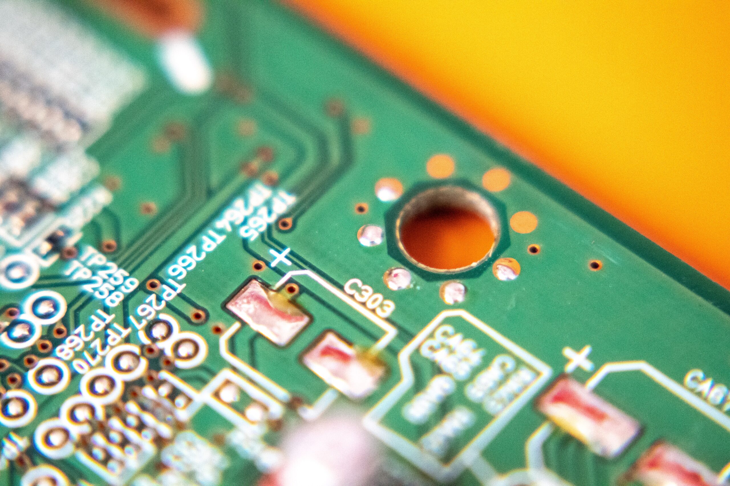
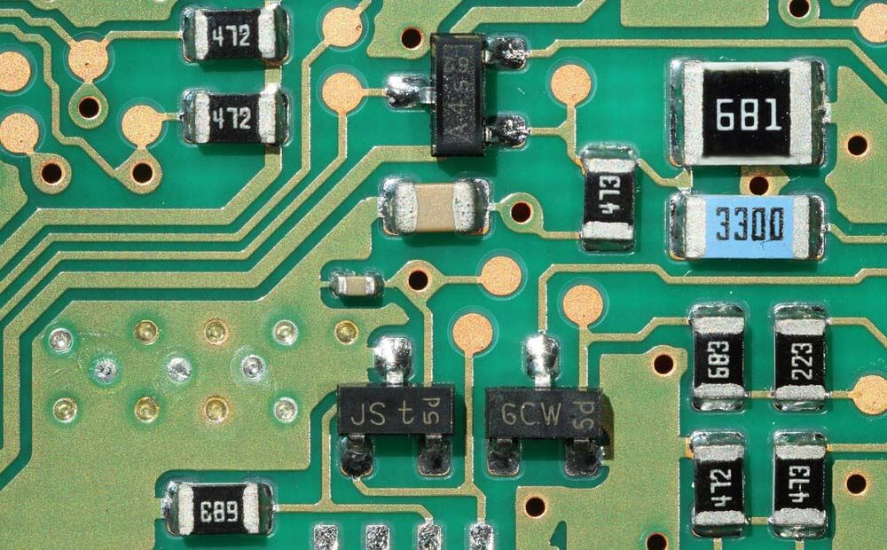
When working with microcontrollers, sensors, development boards, and bare printed circuit boards, most engineers pay close attention to power supply voltage, soldering temperature, component orientation, and signal integrity. One risk, however, is much easier to overlook: electrostatic discharge.
A person walking across a floor, moving on a chair, removing packaging, or handling plastic materials can accumulate static charge. The discharge may be too small to see or feel, yet sensitive semiconductor devices can still be exposed to potentially damaging electrical stress.
For hobby projects, a damaged component may simply result in a board that no longer works. In electronics manufacturing and PCB assembly, the consequences can be more complicated. Electrostatic damage can sometimes contribute to immediate failure, while in other cases a stressed device may continue operating but become less reliable.
This is why an ESD-safe workbench should be treated as a complete system rather than simply a table covered with an anti-static surface.
What Makes an Electronics Workbench ESD-Safe?
A practical ESD-controlled workstation normally combines several elements:
- A static-dissipative work surface
- A defined grounding path
- A wrist strap for the operator when appropriate
- A common grounding point
- ESD-safe storage and handling materials
- Grounded or ESD-compatible tools
- Ionization where isolated conductors or insulating materials create additional risks
- Periodic resistance and continuity verification
The purpose is not to make every object perfectly conductive.
Instead, the objective is to control charge generation and provide predictable paths for accumulated charge to dissipate without creating uncontrolled discharge events around sensitive electronics.
This distinction is important.
Simply placing a PCB on a surface marketed as "anti-static" does not automatically create an ESD-protected workstation.
1. Start With the Work Surface
The work surface is one of the most important parts of an electronics workstation because PCBs, components, tools, and assemblies frequently come into direct contact with it.
A proper ESD mat is designed to help control electrostatic charge while providing a suitable surface for electronics assembly, inspection, testing, and repair.
Bench mats are commonly manufactured using rubber, vinyl, or other engineered static-control materials. In professional environments, multi-layer rubber constructions are frequently used because the layers can be designed to provide different electrical and mechanical characteristics.

For example, the upper layer may provide a durable static-dissipative working surface while another layer contributes to the electrical path toward ground.
When choosing a work surface, consider more than its color or the presence of an ESD symbol.
Important parameters include:
- Surface resistance
- Resistance to ground
- Point-to-point resistance
- Material construction
- Thickness
- Heat resistance
- Chemical resistance
- Abrasion resistance
- Grounding connection
- Long-term resistance stability
For soldering and PCB repair benches, heat and wear resistance can be especially important because the surface is routinely exposed to tools, flux residues, components, and repeated cleaning.
2. Ground the Work Surface Correctly
An ESD mat cannot provide its intended charge-dissipation path if it is installed without an appropriate ground connection.
A typical setup includes a grounding snap installed on the mat, a grounding cord, and a connection to an approved grounding point.
The basic path can be visualized as:
Work Surface → Grounding Snap → Ground Cord → Common Grounding Point → Ground
This allows charge accumulated on the work surface to dissipate through a controlled path.

One common mistake is assuming that placing an ESD mat on a metal table automatically grounds the mat. Another is attaching the grounding cord to an arbitrary metal structure without verifying whether that structure actually provides the required grounding reference.
Ground connections should therefore be intentionally designed and verified.
3. Control Charge on the Operator
The workbench is only part of the system.
People are significant sources of electrostatic charge because ordinary movement can create charge through contact and separation between materials.
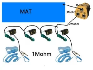
When handling ESD-sensitive devices at a workstation, a wrist strap is commonly used to connect the operator to the workstation's grounding system through a controlled path.
A basic configuration is:
Operator → Wrist Strap → Coil Cord → Common Grounding Point
The mat and operator can therefore share the same grounding reference.
The wrist strap should fit properly and maintain reliable contact with the skin. A loose strap, damaged cord, or incorrect connection can make the system ineffective even though the operator appears to be wearing ESD protection.
In professional environments, wrist straps and their cords should be checked periodically rather than assumed to remain functional indefinitely.
4. Use a Common Grounding Point
A common grounding point helps organize the grounding system and reduces the possibility of different workstation elements being connected to unrelated references.
A typical electronics workstation may connect the following to a common point:
- ESD work surface
- Wrist strap
- Compatible accessories
- Other approved grounding connections
The goal is equipotential control.
When the operator, work surface, and relevant conductive objects are maintained at similar electrical potential, the probability of an uncontrolled discharge between them can be reduced.
For a small microcontroller development bench, the system may be relatively simple. In a production environment, however, grounding architecture should follow the facility's ESD control program and applicable procedures.
5. Don’t Forget Tools and Storage
Even a correctly grounded mat cannot compensate for poor handling practices elsewhere.
A PCB may move through several locations before reaching the bench:
Storage → Transport → Assembly → Programming → Testing → Inspection → Packaging
Static-control practices should therefore extend beyond the work surface.
Sensitive components may require ESD-safe trays, conductive or static-dissipative containers, shielding bags, or other appropriate packaging.
Tools also deserve attention.
Soldering stations, tweezers, component bins, PCB holders, and test equipment should be selected and used according to the requirements of the ESD-controlled area.
Ordinary plastic containers are particularly easy to overlook. Some insulating materials can retain electrostatic charge and cannot be made safe simply by connecting a grounding wire to them.
6. Understand When Ionization Is Needed
Grounding is highly effective for conductors and people that can be connected to ground, but insulating materials create a different problem.
An insulator may hold localized charge because that charge cannot move freely through the material.
This is where ionization can become useful.
An ESD ionizer produces positive and negative ions that help neutralize electrostatic charge on surfaces that cannot be effectively grounded.
Ionizers may be useful around:
- Plastic housings
- Films
- Insulating fixtures
- Certain packaging materials
- Displays
- Nonconductive assembly components
An ionizer should not be considered a substitute for proper grounding. It addresses a different part of the static-control problem.
7. Verify the Workbench Instead of Assuming It Works
One of the most important differences between a casual anti-static setup and a controlled ESD workstation is verification.
A mat may look perfect while its electrical performance has changed because of contamination, wear, incorrect grounding, cleaning residues, or damage.
This is why resistance testing matters.
Two useful measurements for work surfaces are resistance-to-ground (RTG) and point-to-point resistance (PTP).
Resistance to Ground
RTG evaluates the electrical path between a selected location on the work surface and the workstation grounding connection.
Conceptually:
Test Electrode → Mat → Grounding Connection
This measurement helps determine whether charge on the work surface has an appropriate path toward ground.
Point-to-Point Resistance
PTP measures resistance between two locations on the surface.
Conceptually:
Electrode A → Work Surface → Electrode B
This can help evaluate electrical consistency across the mat and identify localized problems.
A detailed procedure for how to test an ESD mat can be useful when establishing a repeatable inspection routine, particularly when documenting electrode placement, test voltage, environmental conditions, and measured values.
8. Test More Than One Location
Testing only one convenient location can hide problems.
Consider measuring several areas of the work surface, such as:
- Center
- Front left
- Front right
- Rear area
- A point relatively far from the grounding connection
Multiple measurements make it easier to detect contamination, uneven wear, localized damage, or inconsistent resistance.
For repeatable testing, document:
- Date
- Workstation identification
- Instrument
- Test method
- Test voltage
- Electrode locations
- Temperature
- Relative humidity
- RTG results
- PTP results
- Pass/fail assessment
The exact acceptance criteria should come from the ESD control requirements applicable to the facility rather than from an arbitrary number found online.
9. Keep the Surface Clean
Contamination can affect the electrical behavior of an ESD work surface.
Common contaminants include:
- Dust
- Oil
- Flux residue
- Adhesives
- Food and drink residues
- Incorrect cleaning chemicals
A cleaning product that leaves an insulating film may change surface behavior even if the mat looks cleaner afterward.
For this reason, maintenance procedures should consider both cleanliness and electrical performance.
After significant cleaning or maintenance, resistance testing can help confirm that the surface still performs as expected.
10. Common ESD Workbench Mistakes
Many ESD problems come from installation and maintenance errors rather than from the absence of ESD products.
Common mistakes include:
Using an ESD mat without grounding it.
The surface may be designed for static control, but without the intended ground path the workstation is incomplete.
Grounding to an unverified metal object.
Metal does not automatically mean electrical ground.
Wearing a wrist strap without testing it.
A broken conductor or poor skin contact can defeat the intended protection.
Using ordinary plastic storage bins near sensitive components.
Insulating materials can accumulate charge and may require replacement, separation, or ionization.
Assuming an old mat still meets requirements.
Appearance alone cannot confirm resistance performance.
Testing only once after installation.
Workstations change over time because of wear, contamination, maintenance, and modifications.
A Practical Workbench Layout
For a microcontroller or PCB development bench, a practical arrangement could include an ESD work surface covering the main assembly area, a verified grounding connection, a common grounding point positioned where it can be inspected easily, and a wrist-strap connection accessible to the operator.
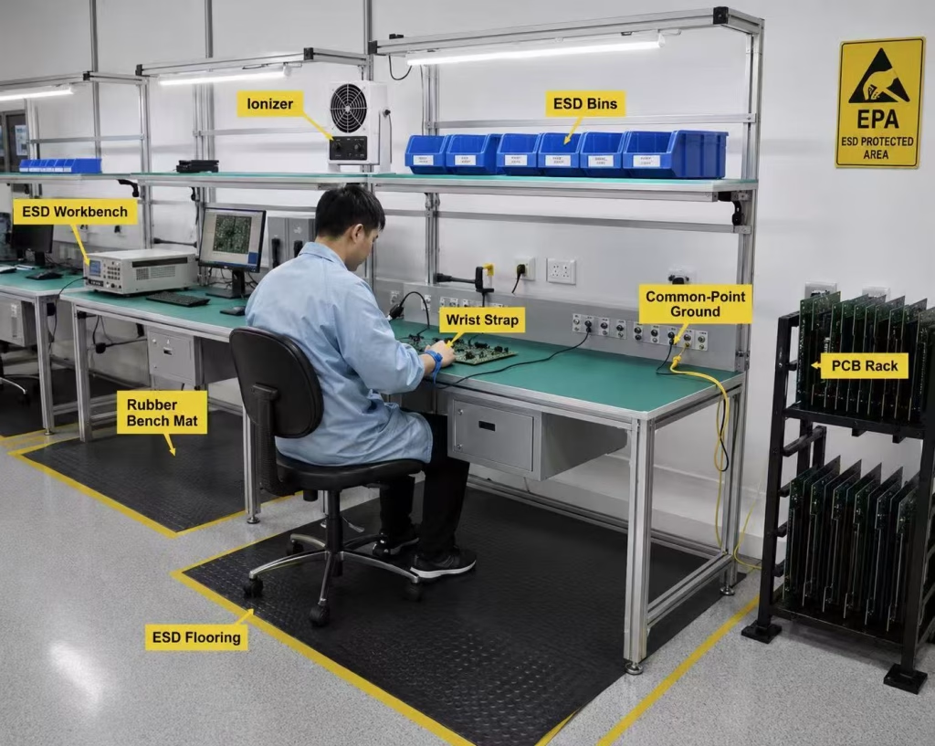
ESD-safe component storage can be positioned nearby, while soldering and test equipment should be arranged so that cables do not interfere with the grounding system.
If insulating materials must remain inside the work area, ionization can be considered based on the ESD control requirements.
The final step is verification.
The workstation should not merely look ESD-safe. Its critical elements should be testable.
Final Thoughts
Building an ESD-safe electronics workbench does not require making every surface conductive or adding as many ESD accessories as possible.
The important principle is controlled electrostatic potential.
A good workstation combines an appropriate work surface, a verified grounding path, operator grounding, suitable handling materials, and periodic testing.
For electronics engineers, makers, and technicians working with microcontrollers and PCBs, this approach adds another layer of process control to the bench.
We routinely verify voltage before powering a circuit, inspect solder joints before testing a board, and check continuity when troubleshooting a connection.
ESD control deserves the same engineering mindset:
Do not assume. Measure, verify, and maintain.