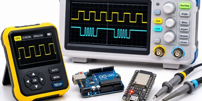
One of the most popular pocket oscilloscopes is about the size of a deck of cards. The FNIRSI DSO152 offers 200 kHz of bandwidth, raising a fair question: is a cheap handheld scope enough for Arduino and ESP32 work, or do you need a bench instrument?
The answer depends on the signal you want to inspect. A pocket oscilloscope can reveal PWM and servo pulses, but I2C, SPI and fast serial data demand more bandwidth, more channels or both. You also need to distinguish between seeing that a waveform exists and measuring its shape accurately.
In this guide, I compare four oscilloscopes and a USB logic analyzer using their published specifications, signal timing calculations and independent reviews. I have not tested these instruments side by side.
Quick Answer: The Best Oscilloscope for Arduino and ESP32
A cheap handheld oscilloscope works for PWM, servo control and slower serial activity. If you regularly debug I2C or SPI, a two-channel handheld or a bench oscilloscope is a more useful investment.
| What you debug | Instrument | Bandwidth / channels | Why choose it? | Details |
|---|---|---|---|---|
| PWM, servos and slow UART | FNIRSI DSO152 | 200 kHz / 1 | Compact, low-cost signal checking | See below |
| I2C, UART and LED strip data | FNIRSI 2C53T | 50 MHz / 2 | Two traces, multimeter and signal generator | See below |
| SPI and longer acquisitions | Rigol DHO804 | 70 MHz / 4 | Four channels, 12-bit ADC and bus decoding | See below |
| Faster ESP32 SPI | Siglent SDS1202X-E | 200 MHz / 2 | Higher bandwidth and serial decoding | See below |
| Finding bytes on a bus | 24 MHz USB logic analyzer | 8 digital inputs | Decoding several digital lines on a computer | See below |
How Fast Are Arduino and ESP32 Signals?
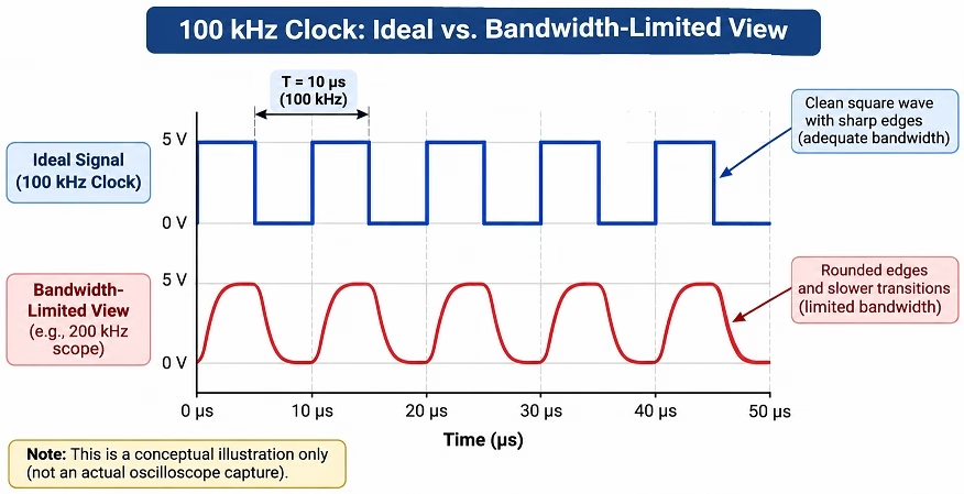
Bandwidth is the first specification to check. As a practical starting point for digital signals, Keysight recommends choosing oscilloscope bandwidth around five times the signal's fundamental frequency. Digital edges contain higher-frequency harmonics, so a scope with limited bandwidth may show activity but round the edges and distort timing measurements.
The table below applies that rule to familiar microcontroller signals. These are indicative calculations, not measurements of the listed oscilloscopes. For UART, the alternating-bit pattern has a fundamental frequency equal to half the bit rate. For a servo signal, the roughly 50 Hz repetition rate does not describe its edge speed; the scope still needs enough bandwidth to resolve the pulse transitions.
| Signal | Typical rate | Approximate bandwidth target | DSO152 | 2C53T |
|---|---|---|---|---|
| Servo control pulses | About 50 pulses/s, 1–2 ms high | Edge-speed dependent | Pulse width visible | Yes |
Arduino Uno analogWrite() PWM |
About 490 or 980 Hz | About 2.5–5 kHz for fundamental × 5 | Yes | Yes |
| ESP32 LEDC PWM example | 5 kHz | 25 kHz | Yes | Yes |
| UART at 9600 baud | 9,600 bits/s | 24 kHz | Yes | Yes |
| UART at 115200 baud | 115,200 bits/s | 288 kHz | Readable with rounded edges | Yes |
| I2C standard mode | 100 kHz clock | 500 kHz | Activity only | Yes |
| I2C fast mode | 400 kHz clock | 2 MHz | No | Yes |
| WS2812 / NeoPixel data | 800 kbit/s | About 4 MHz as a rule of thumb | No | Yes |
| Arduino Uno SPI, common default | 4 MHz clock | 20 MHz | No | Yes |
| Arduino Uno SPI, up to | 8 MHz clock | 40 MHz | No | Near bandwidth limit |
| ESP32 SPI example | 20 MHz clock | 100 MHz | No | No, for accurate edges |
Why the Number of Channels Matters
Bandwidth is not the only limitation. I2C has a clock line (SCL) and a data line (SDA), so two channels let you view their timing together. For a typical four-wire SPI connection, four channels can show SCLK, MOSI, MISO and chip select at the same time. A PWM output usually needs only one.
Pocket Scope: What the FNIRSI DSO152 Can and Cannot Show
My pick for checking simple signals: FNIRSI DSO152.
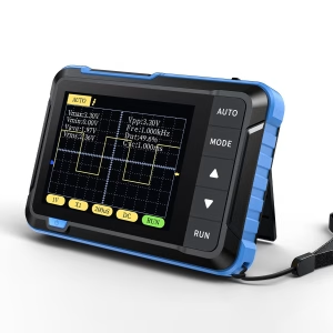
The FNIRSI DSO152 has one channel, 200 kHz bandwidth and a 2.5 MSa/s sampling rate. The maker estimates around four hours of battery use. Those modest specifications still cover several beginner tasks:
- PWM: The 490 Hz and 980 Hz outputs commonly generated by
analogWrite()on an Arduino Uno are well within its range. See our Arduino 16-bit PWM tutorial. - Servo pulses: You can inspect the roughly 1–2 ms pulse widths that repeat around every 20 ms.
- Slow UART: At 9600 baud, each bit lasts about 104 µs. See our microcontroller serial communication guide.
- Motor drive: You can check the PWM enable signal used in the L298N motor driver tutorial.
Fast digital buses expose its limitations. A 100 kHz I2C clock may look severely rounded, and a single channel cannot display SCL and SDA together. An independent DSO152 bench comparison shows why this is better treated as a quick signal checker than a bus-debugging instrument.
Check the package variant, too. Some DSO152 bundles include a clip lead only, while others add a P6100 switchable 1×/10× probe.
Two-Channel Handheld: What the FNIRSI 2C53T Adds
My pick for most Arduino and ESP32 hobby projects: FNIRSI 2C53T.
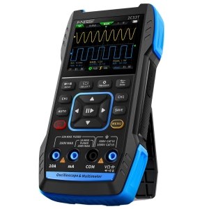
The FNIRSI 2C53T combines a claimed 50 MHz oscilloscope, 250 MSa/s maximum sampling rate, a digital multimeter and a signal generator rated up to 50 kHz. Two input channels make it substantially more useful than a one-channel pocket scope.
You can connect SCL to channel 1 and SDA to channel 2, or compare a PWM command with a corresponding output signal. Its bandwidth also gives you room to inspect 115200-baud UART, WS2812 data and SPI running at a few megahertz. That includes ESP32 LEDC PWM such as the heater control discussed in our ESP32 PID controller tutorial.
What Independent Reviews Found
Published reviews give a more balanced picture than the specifications alone:
- Elektor: Harry Baggen's review reported usable response through the nominal 50 MHz range.
- element14: An August 2026 characterization demonstrated signal acquisition across 1–50 MHz but found errors in some automatic frequency readings.
- atomic14: Its bench listing treats the device primarily as a field tool and cautions about optimistic specifications.
Read the waveform and time grid rather than trusting every automatic measurement. The international product listing specifies 1 Kpoint record depth and no built-in protocol decoder; check the exact revision and listing because regional documentation can differ. For capturing long messages and decoding the bytes automatically, a bench scope or logic analyzer is better.
Bench Scopes: When Rigol or Siglent Is Worth the Money
Rigol DHO804: My Pick for a First Bench Scope
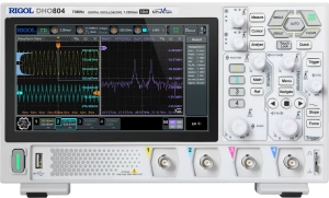
The Rigol DHO804 has four analog channels, 70 MHz bandwidth and a 12-bit vertical converter. Its maximum sampling rate is 1.25 GSa/s with one channel active. For regular SPI debugging, these features make a difference:
- Four analog channels: Monitor chip select, clock, MOSI and MISO together.
- Serial decoding: Decode UART, I2C and SPI traffic on the instrument.
- Deep acquisition memory: Rigol's datasheet lists up to 25 Mpoints with one active channel, 10 Mpoints with two, and 5 Mpoints with all four active.
A 12-bit ADC represents 4,096 quantization steps compared with 256 for an 8-bit ADC. Whether that translates into more useful detail depends on noise, probes and the measurement setup, but it is a welcome advantage when checking small signals or ripple.
Siglent SDS1202X-E: More Bandwidth for Fast SPI
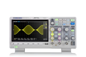
If your ESP32 design clocks SPI at 20 MHz, applying the five-times rule points toward roughly 100 MHz or more bandwidth for a cleaner view of its transitions. The Siglent SDS1202X-E offers 200 MHz across two channels, with a maximum 1 GSa/s sampling rate and up to 14 Mpoints record depth. Siglent includes serial bus triggering and decoding as standard.
This is a useful choice for timing measurements on faster lines, but remember that two analog channels cannot display every line of a four-wire SPI bus simultaneously. Sampling rate and record depth can also depend on how many channels are active.
The older Rigol DS1054Z remains recognizable, but the DHO804 offers a newer 12-bit acquisition system and more nominal bandwidth than the original 50 MHz DS1054Z.
Oscilloscope or Logic Analyzer?
An oscilloscope plots voltage against time. It can reveal slow transitions, ringing, noise and incorrect voltage levels. A logic analyzer captures digital HIGH and LOW states, often across several inputs, and decodes protocol frames into addresses and data bytes.
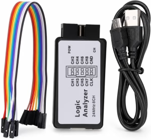
A common 24 MHz, eight-channel USB logic analyzer, used with compatible PulseView software, can be more convenient for inspecting I2C, UART and modest-speed SPI transactions than reading individual bits on an oscilloscope. Check the particular analyzer's supported sampling rate, voltage thresholds and software compatibility; inexpensive listings are not all equivalent.
It cannot tell you why a supposedly HIGH signal is stuck at an intermediate voltage. That matters especially when connecting 5 V Arduino hardware to 3.3 V microcontrollers. Our 3.3 V versus 5 V logic-level guide explains what to check.
If your immediate problem involves bytes and protocol timing, begin with a logic analyzer. If it involves voltage levels, pulse shape, PWM or analog behavior, reach for an oscilloscope.
What to Check Before Buying an Oscilloscope
Before choosing a listing, check the following:
- Bandwidth: Consider your fastest clock and how accurately you need to see its edges. Five times the signal frequency is a useful starting point, not a guarantee for every edge rise time.
- Sampling rate: The headline figure is usually a maximum. Check what happens when more channels are enabled.
- Channels: One for a simple PWM output, two to compare I2C clock and data, or four to observe a typical SPI bus together.
- Memory depth: Deeper capture records are particularly helpful if you need to zoom into a long transaction after triggering.
- Probe bundle: A suitable 10× probe and short ground connection can make a major difference when inspecting faster signals.
- Electrical safety: Check the instrument, probe and ground-lead ratings. Ordinary grounded bench-scope probe clips must never be attached arbitrarily to live mains or other non-isolated high-voltage circuits. The examples here concern low-voltage microcontroller systems.
Frequently Asked Questions
Is the FNIRSI DSO152 good enough for Arduino?
For basic PWM, servo pulses and slower UART signals, yes. Its single channel and 200 kHz bandwidth make it a poor choice for detailed I2C and SPI debugging.
What is the best oscilloscope for Arduino beginners?
The FNIRSI 2C53T is a versatile option if you expect to work with I2C sensors, displays or a mixture of digital and analog signals. The DSO152 costs less if you only want to check slow waveforms.
How much bandwidth do I need for an ESP32?
It depends on the peripheral. A 50 MHz scope is ample for many PWM, UART and I2C tasks. For a 20 MHz SPI clock, about 100 MHz is a reasonable starting target if edge fidelity matters.
Do I need an oscilloscope if I already own a logic analyzer?
Not necessarily for protocol decoding, but an oscilloscope answers different questions. It reveals analog voltage problems and transition quality that a digital-only analyzer may hide.
Conclusion
The best oscilloscope for Arduino and ESP32 work depends more on your signals than on the highest specification printed on a product page. Choose the FNIRSI DSO152 for simple PWM and pulses, the two-channel FNIRSI 2C53T for mixed hobby projects, the four-channel Rigol DHO804 for regular bus debugging, or the 200 MHz Siglent SDS1202X-E when faster SPI edges matter. A USB logic analyzer is a useful companion for decoding actual data.
If you want practice signals, try our Arduino PWM tutorial, L298N motor-driver guide or ESP32 PID tutorial.