
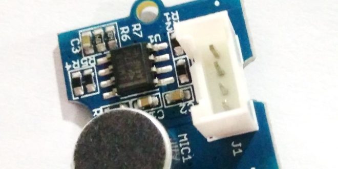
How can an Arduino detect sound? The simplest way is to use a microphone module, often sold as an Arduino sound sensor. These small boards usually include an electret microphone, a few support components, and an amplifier circuit that turns sound vibrations into a voltage the Arduino can read.
In this tutorial, you’ll learn how a microphone sound sensor works, how to connect it to an Arduino, how to view sound levels in the Serial Plotter, and how to build a simple clap switch. This is a good beginner project because it introduces analog input, sensor noise, threshold detection, and basic sound-triggered control.
However, it is important to understand one limitation right away: a basic microphone module cannot understand speech by itself. It can detect sound level changes, loud noises, claps, knocks, or silence, but it cannot recognize words unless you add more processing hardware or send the audio data to a computer.
What Is an Arduino Microphone Module?
An Arduino microphone module is a small circuit board that lets a microcontroller detect sound. Most beginner sound sensor boards use an electret microphone. Examples include Grove sound sensors, SunFounder sound sensors, KY-037/KY-038-style modules, and many similar boards.
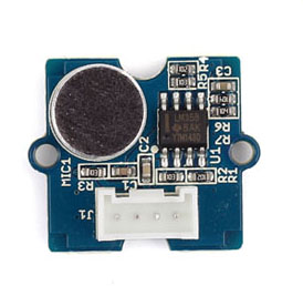
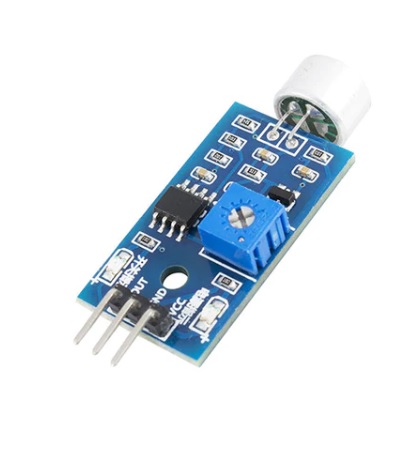
These modules usually have three important parts:
- Electret microphone — converts sound vibrations into a tiny electrical signal.
- Amplifier circuit — boosts the weak microphone signal.
- Output pin — sends the signal to the Arduino.
Some modules only provide an analog output. Others provide both analog and digital outputs. In this tutorial, we will focus on the analog output because it gives you more useful information about the sound level.
How an Electret Microphone Works
Most sound sensor boards use an electret microphone capsule. An electret microphone is a type of condenser microphone. A condenser microphone works like a tiny capacitor, which is made from two conductive surfaces separated by an insulating material.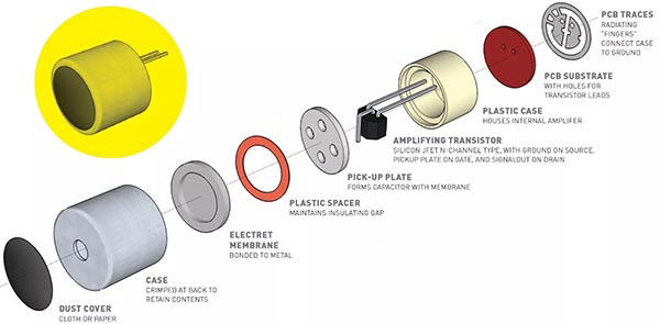
Inside the microphone, one of these conductive surfaces is a very thin diaphragm. When sound reaches the microphone, the diaphragm vibrates. As it moves, the distance between the diaphragm and the other plate changes. Because capacitance depends partly on the distance between the two plates, the microphone produces a small changing electrical signal.
A regular condenser microphone often needs a higher external voltage to maintain its charge. In contrast, an electret microphone uses a special permanently charged material. This material keeps a built-in charge, so the microphone can work with a much simpler circuit.
Still, the signal from the microphone capsule is very small. Therefore, most Arduino sound sensor boards include an amplifier, commonly based on an LM358 or a similar op-amp. The amplifier makes the signal large enough for the Arduino’s analog input to detect.
Analog vs Digital Sound Sensor Outputs
Many microphone modules have pins labeled something like:
- VCC
- GND
- AO or AOUT
- DO or DOUT
The analog output gives a changing voltage that represents the detected sound level. This is the best pin to use when you want to see sound intensity, plot the signal, or choose your own threshold in software.
The digital output usually comes from a comparator circuit. It switches HIGH or LOW when the sound level crosses a set threshold. Some boards include a small potentiometer that lets you adjust this threshold. This output is useful for very simple projects, but it gives less information than the analog output.
For a clap switch, either output can work. However, using the analog output gives you more control and helps you understand what the sensor is actually measuring.
Parts Needed
For this project, you will need:
- Arduino Uno or compatible board
- Microphone sound sensor module
- LED, or the built-in LED on pin 13
- Jumper wires
- Breadboard, optional
You can use the Arduino Uno’s built-in LED for the clap switch example. Because of that, the basic version does not need an external LED.
Arduino Microphone Wiring
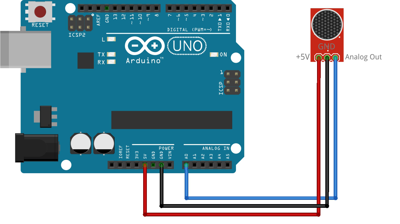
Connect the sound sensor module to the Arduino like this:
| Sound Sensor Pin | Arduino Pin |
|---|---|
| VCC | 5V |
| GND | GND |
| AO / AOUT | A0 |
Most common sound sensor modules work with 5V, which makes them easy to use with an Arduino Uno. However, always check your module’s label or datasheet. Some modules may also work at 3.3V, but the output level and sensitivity can change.
After wiring the sensor, place it away from strong electrical noise sources such as motors, relays, and long unshielded wires. Otherwise, the readings may jump even when there is no loud sound.
Reading Sound Level with Arduino
The Arduino reads analog voltage using its built-in analog-to-digital converter. On an Arduino Uno, analogRead() returns a value from 0 to 1023. A value near 0 means the input voltage is close to 0V, while a value near 1023 means it is close to 5V.
Here is a simple sketch that reads the sound sensor on pin A0 and prints the averaged value to the Serial Plotter:
const int soundPin = A0;

void setup()
{
  Serial.begin(9600);
}

void loop()
{
  long sum = 0;

  for (int i = 0; i < 100; i++)
  {
     sum += analogRead(soundPin);
  }

  int averageValue = sum / 100;

  Serial.println(averageValue);

  delay(10);
}
This sketch takes 100 readings and averages them. As a result, the displayed value becomes more stable. However, it will still move around because sound is naturally changing all the time.
Upload the sketch, then open Tools > Serial Plotter in the Arduino IDE. You should see the sensor output moving as the microphone detects ambient sound.
Understanding the Serial Plotter Output
Do not expect a perfectly flat line. Even in a quiet room, the sensor may show changing values because it can pick up background noise, electrical noise, and small vibrations.
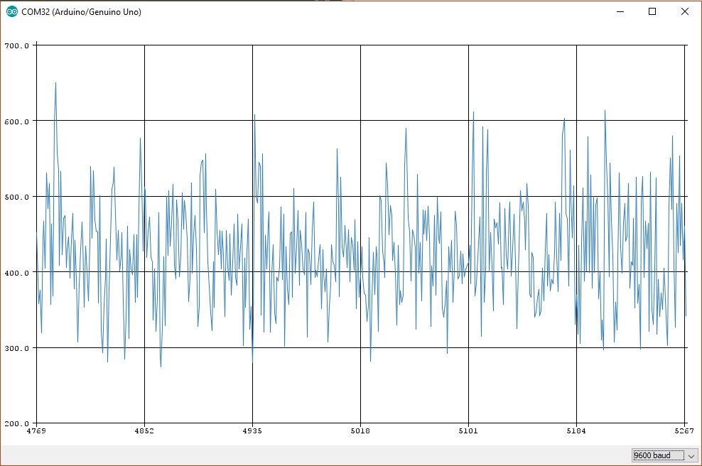
For example, your readings may normally stay around 300 to 500. Then, when you clap near the sensor, the value may quickly jump above 600 or 700. The exact numbers depend on the module, the room, the distance from the sound source, and the sensor’s built-in gain.
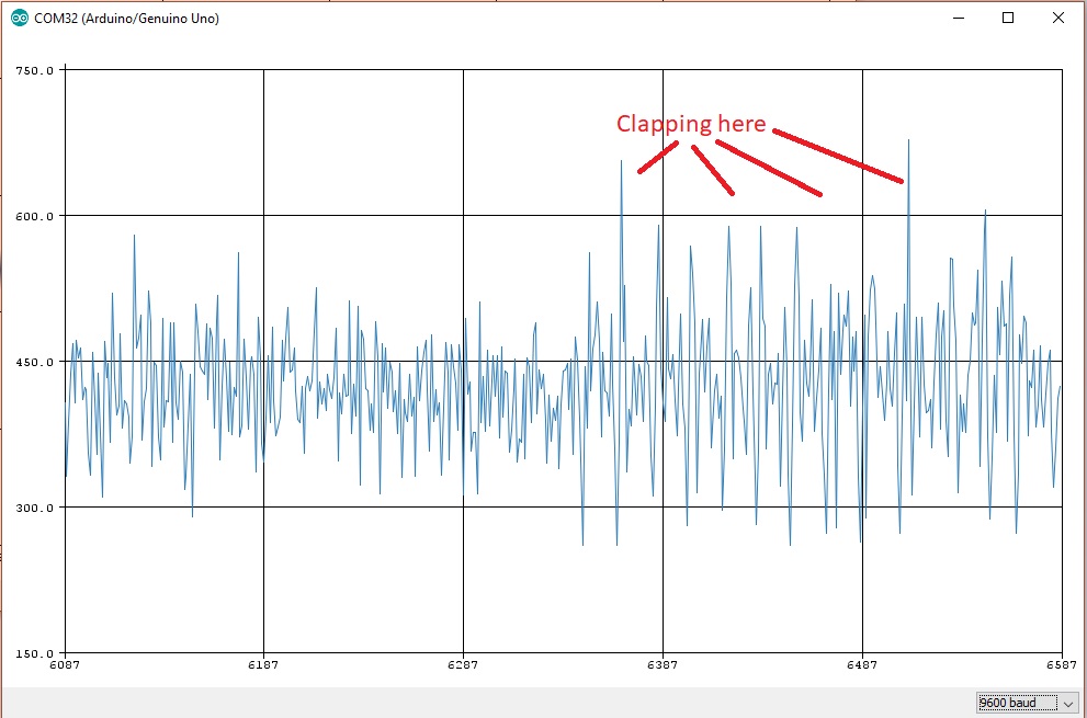
Because every setup is different, you should test your own sensor before choosing a threshold. Open the Serial Plotter, watch the normal background level, then clap or make a loud sound. Choose a threshold that is clearly above the normal noise level but below the clap peak.
For example, if the quiet readings stay below 520 and a clap reaches 700, a threshold around 600 may work well.
Making a Simple Clap Switch
Now that we know how to detect a loud sound, we can use the microphone module to control an LED. The following sketch turns on the built-in LED when the sound level rises above a threshold:
const int soundPin = A0;
const int ledPin = 13;

const int soundThreshold = 600;

void setup()
{
  Serial.begin(9600);
  pinMode(ledPin, OUTPUT);
}

void loop()
{
  long sum = 0;

  for (int i = 0; i < 100; i++)
  {
    sum += analogRead(soundPin);
  }

  int averageValue = sum / 100;

  if (averageValue > soundThreshold)
  {
    digitalWrite(ledPin, HIGH);
  }
  else
  {
    digitalWrite(ledPin, LOW);
  }

  Serial.println(averageValue);

  delay(10);
}
When the sensor detects a loud enough sound, the LED turns on. Otherwise, the LED stays off. This is the simplest version of a clap switch.
However, this version does not latch the LED state. In other words, the LED only stays on while the sound level is above the threshold. For a real clap switch, you usually want the LED to toggle ON after one clap and toggle OFF after another clap.
Toggle LED with a Clap
Here is a better version of the project. This sketch changes the LED state every time a clap is detected:
const int soundPin = A0;
const int ledPin = 13;

const int soundThreshold = 600;
const unsigned long debounceTime = 300;

bool ledState = false;
unsigned long lastClapTime = 0;

void setup()
{
  Serial.begin(9600);
  pinMode(ledPin, OUTPUT);
}

void loop()
{
  long sum = 0;

  for (int i = 0; i < 100; i++)
  {
    sum += analogRead(soundPin);
  }

  int averageValue = sum / 100;

  if (averageValue > soundThreshold)
  {
    unsigned long currentTime = millis();

   if (currentTime - lastClapTime > debounceTime)
   {
     ledState = !ledState;
     digitalWrite(ledPin, ledState);
     lastClapTime = currentTime;
   }
  }

  Serial.println(averageValue);

  delay(10);
}
This version uses a short delay window called debounceTime. Without it, one clap might be detected several times because the sound does not appear as a single clean spike. Instead, it may create several high readings in a short period.
The millis() check prevents the Arduino from counting the same clap repeatedly.
Adjusting the Clap Sensitivity
The most important value in this project is:
const int soundThreshold = 600;
You may need to change this number. If the LED turns on too easily, increase the threshold. If the LED does not react to claps, lower the threshold.
A good way to tune the threshold is:
- Upload the first Serial Plotter sketch.
- Watch the normal room noise level.
- Clap near the microphone and note the peak value.
- Choose a threshold between the normal level and the clap peak.
- Test again and adjust as needed.
For example, if the room noise stays around 450 and a clap reaches 750, you can try a threshold of 600. On the other hand, if your sensor only reaches 580 during a clap, try a lower value such as 520.
Common Problems
The readings do not change
Check the wiring first. Make sure the sensor’s analog output is connected to A0, not the digital output pin. Also, confirm that VCC and GND are connected correctly.
The readings are always too high
Some modules have an adjustable potentiometer, but it may only affect the digital output. If the analog readings are still too high, try moving the sensor away from noise sources or lowering the sound threshold in your sketch.
The LED turns on randomly
Your threshold may be too low. Increase the threshold and test again. Also, check for background noise such as fans, motors, tapping on the table, or nearby speakers.
The clap switch triggers multiple times
Use a debounce delay with millis(), as shown in the toggle example. A clap can produce several peaks, so the Arduino needs a short lockout period after each detection.
Can Arduino Record Audio?
A basic Arduino Uno is not ideal for recording audio. Although it can read analog values from a microphone module, it has limited memory, limited sampling speed, and no built-in audio storage system.
For simple sound level detection, the Arduino Uno works fine. For actual audio recording, speech recognition, or frequency analysis, you will usually need a more capable board or additional hardware.
Better options include:
- ESP32 with I2S microphone
- Raspberry Pi with USB microphone
- Dedicated voice recognition module
- Computer-based audio processing
- External audio codec or recording module
So, while an Arduino microphone module is excellent for detecting loud sounds, it is not the best choice for projects that need to understand spoken words.
Arduino Microphone Project Ideas
Once you understand the basics, you can use the same sensor in other projects. For example, you can build:
- Sound-activated LED lights
- Knock detector
- Noise level indicator
- Clap-controlled relay
- Sound-triggered alarm
- Simple music beat detector
- Classroom noise monitor
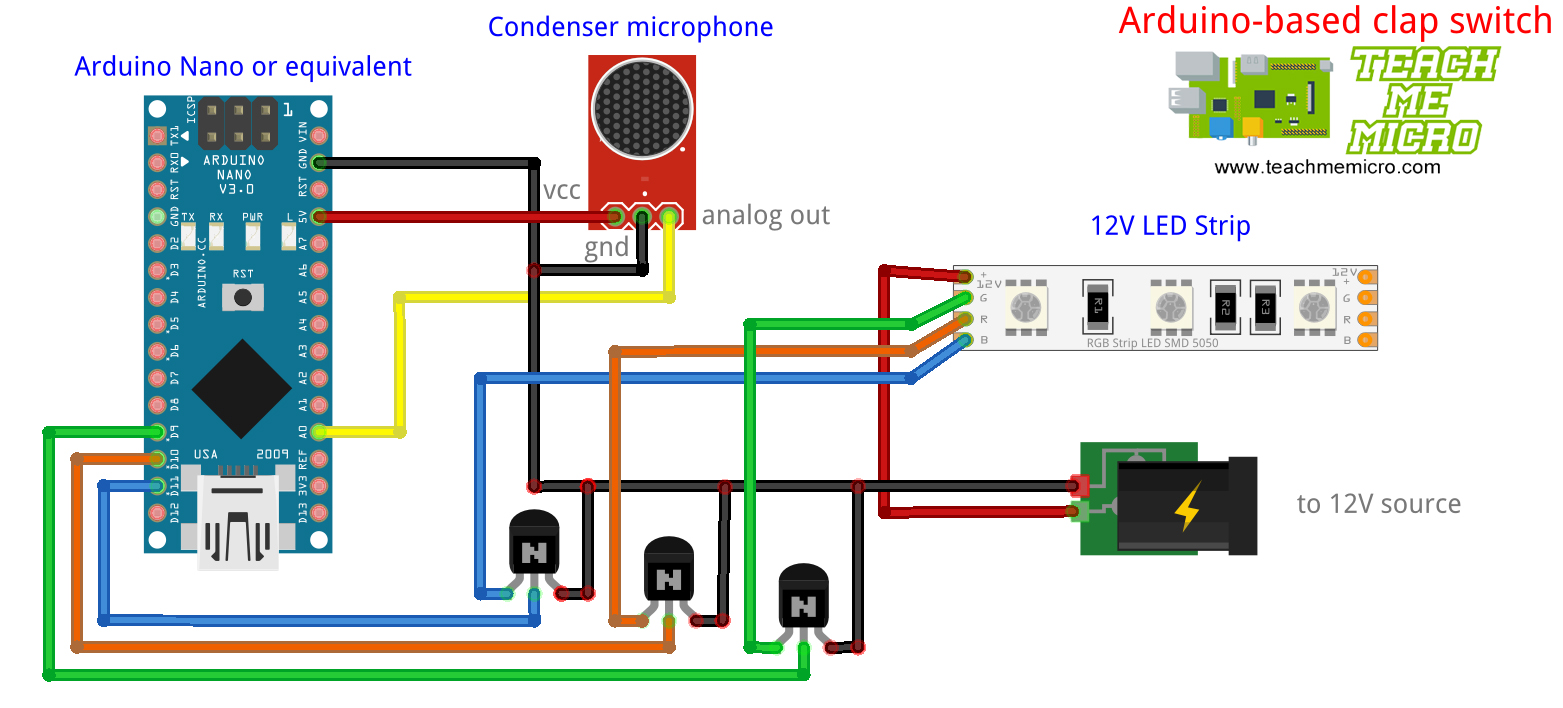
For projects that switch higher loads, such as lamps or appliances, do not connect the load directly to an Arduino pin. Use a relay module, transistor driver, MOSFET, or another suitable switching circuit.
Conclusion
An Arduino can detect sound using a microphone sound sensor module. The module converts sound vibrations into a changing voltage, and the Arduino reads that voltage through an analog input. By watching the values in the Serial Plotter, you can choose a threshold and use it to detect loud sounds like claps.
This setup is simple, affordable, and useful for sound-triggered beginner projects. However, it is mainly for sound level detection, not speech recognition or audio recording. For voice commands or audio processing, you will need more powerful hardware or external processing.
hi!! can i get the circuit of this sketch
what he said^
good good good ~