
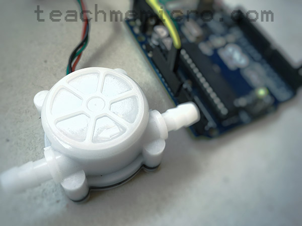
A water flow sensor Arduino project lets you measure how much liquid passes through a tube or pipe. Instead of estimating the water level in a container, the Arduino counts pulses from a flow sensor and converts those pulses into volume and flow rate.
In this tutorial, you will learn how a Hall-effect water flow sensor works, how to wire it to an Arduino UNO, and how to write code that displays both the total water volume and the flow rate in liters per minute.
How Do You Measure Liquid Volume?
There are several ways to measure the volume of a liquid. For example, you can measure the liquid level inside a container with a known cross-sectional area. In that case, an ultrasonic sensor, pressure sensor, or float sensor may be useful.
However, if the liquid is moving through a tube, hose, or pipe, a water flow sensor is often the better choice. Instead of measuring the height of the liquid, the sensor measures how much water passes through it.
Because of this, a flow sensor is useful in projects such as:
- DIY water dispensers
- Irrigation monitoring systems
- Aquarium or hydroponics flow monitoring
- Liquid filling machines
- Water usage counters
- Leak detection systems
- Cooling system flow monitoring
What Is a Water Flow Sensor?
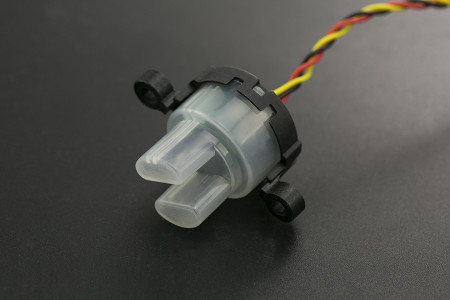
A water flow sensor is a device that produces an electrical signal when liquid flows through it. Most low-cost Arduino water flow sensors use a small turbine or rotor inside the sensor body.
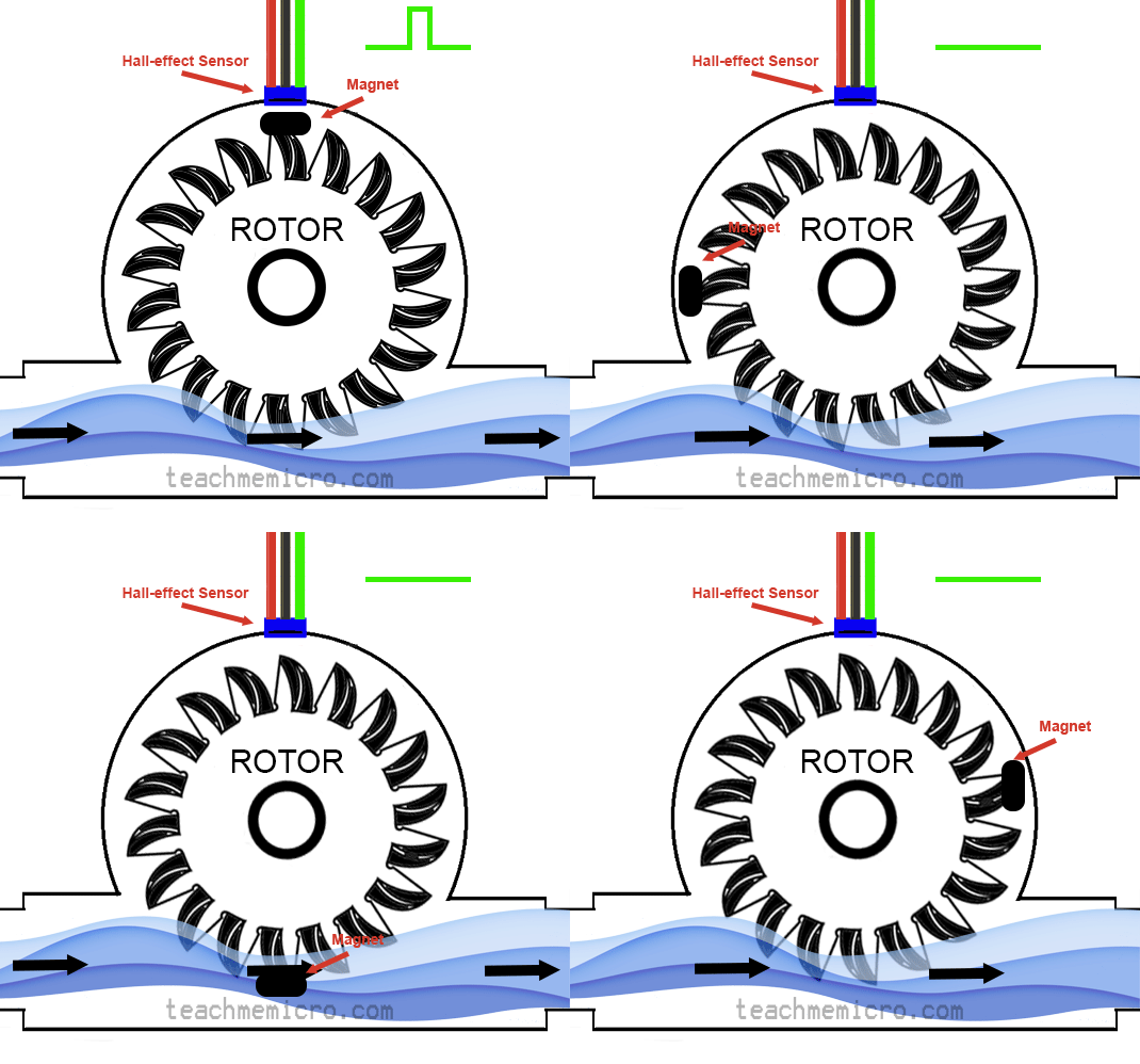
When water enters the sensor, it pushes the turbine and makes it spin. A small magnet is attached to the rotating part. As the magnet passes near a fixed Hall-effect sensor, the sensor produces pulses.
Therefore, the faster the water flows, the faster the turbine spins. As a result, the Arduino receives more pulses per second.
Hall-Effect Sensor Basics
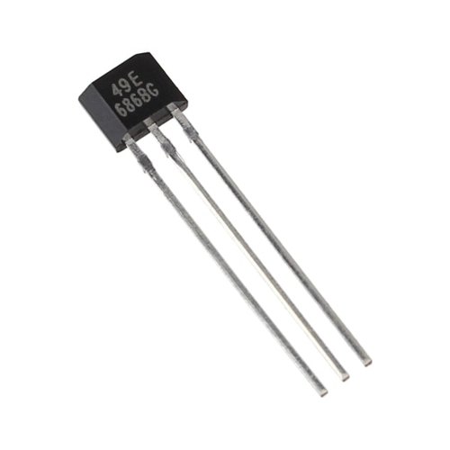
A Hall-effect sensor detects the presence of a magnetic field. In simple terms, when a magnetic field comes close to the sensor, the sensor output changes.
Inside a water flow sensor, the Hall-effect sensor does not directly touch the water. Instead, it detects the magnet attached to the spinning turbine. Every time the magnet passes the Hall-effect sensor, the output pin generates a pulse.
The Arduino can count these pulses using an interrupt pin. Then, by using the sensor’s calibration value, the Arduino can convert the number of pulses into liters.
Water Flow Sensor Pinout
The common water flow sensor used in Arduino projects usually has three wires:
| Wire Color | Pin | Description |
|---|---|---|
| Red | VCC | Power supply |
| Black | GND | Ground |
| Yellow or Green | OUT / Signal | Pulse output |
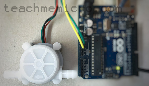
Some modules use a green signal wire, while others use a yellow signal wire. Therefore, always check the label or datasheet of your specific sensor before wiring it.
Water Flow Sensor Specifications
The sensor used in this tutorial has the following specifications:
| Specification | Value |
|---|---|
| Inner diameter | 4 mm |
| Outside diameter | 7 mm |
| Water pressure | Less than 0.8 MPa |
| Water flow range | 0.3 to 6 L/min |
| Voltage range | 5 to 12 V |
| Operating current | 15 mA at 5 V |
| Insulation resistance | Greater than 100 MΩ |
| Accuracy | ±5% from 0.3 to 3 L/min |
| Output pulse high level | Greater than 4.5 V at 5 V input |
| Output pulse low level | Less than 0.5 V at 5 V input |
| Output pulse duty ratio | 50% ±10% |
| Calibration value | 1 liter = 5880 pulses |
| Working humidity | 35% to 90% RH, no frost |
| Dimensions | 58 × 35 × 26 mm |
| Weight | 30 g |
The most important value here is the calibration value:
1 liter = 5880 pulses
This means that if the Arduino counts 5880 pulses, approximately 1 liter of water has passed through the sensor.
However, this value may vary between sensor models. For better accuracy, you should calibrate your own sensor by passing a known amount of water through it and comparing the Arduino reading with the actual volume.
How the Arduino Calculates Water Volume
The formula for total water volume is:
Volume in liters = Number of pulses / Pulses per liter
For this sensor:
Volume in liters = Number of pulses / 5880
For example, if the Arduino counts 2940 pulses:
Volume = 2940 / 5880
Volume = 0.5 L
So, 2940 pulses represent about half a liter of water.
How the Arduino Calculates Flow Rate
Flow rate tells you how fast water is moving through the sensor. In this tutorial, the flow rate is displayed in liters per minute.
To calculate flow rate, the Arduino counts how many pulses occur during a fixed time interval. Then, it converts those pulses into liters.
The formula is:
Flow rate in L/min = (Pulses counted / Pulses per liter) × (60000 / elapsed time in milliseconds)
For example, if the Arduino counts 98 pulses in 1000 milliseconds:
Flow rate = (98 / 5880) × (60000 / 1000)
Flow rate = 1.0 L/min
This method is more stable than measuring only the width of one pulse, especially at low flow rates.
Components Required
For this project, you need:
- Arduino UNO
- Water flow sensor
- Jumper wires
- 6 mm hose or tubing, depending on your sensor
- Water source or container
- Computer with Arduino IDE installed
Water Flow Sensor Arduino Wiring
Connect the water flow sensor to the Arduino as follows:
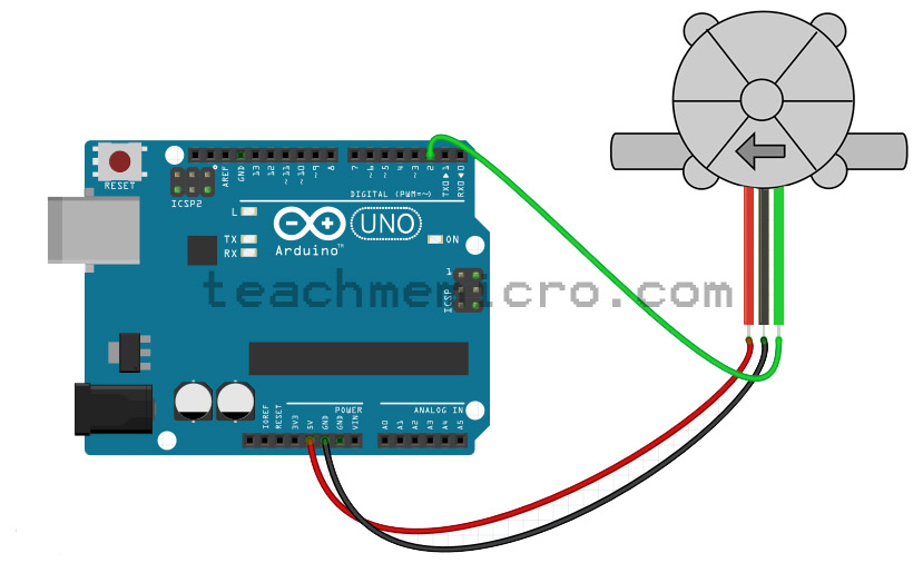
| Water Flow Sensor | Arduino UNO |
|---|---|
| VCC / Red wire | 5V |
| GND / Black wire | GND |
| OUT / Signal wire | Digital Pin 2 |
Digital pin 2 is used because it supports external interrupt 0 on the Arduino UNO. This allows the Arduino to count pulses reliably even while the main loop is doing other tasks.
Important Installation Notes
Water flow sensors work best when the rotor spins freely, and the sensor is installed in the correct direction. Most sensors have an arrow on the body that shows the correct water flow direction.
For best results:
- Follow the flow direction marked on the sensor body.
- Keep the sensor upright when possible.
- Avoid air bubbles in the tube.
- Use a steady water source.
- Do not exceed the sensor’s pressure rating.
- Use the correct hose size for the sensor inlet and outlet.
- Keep the electronics dry.
Also, low-cost flow sensors are not usually designed for drinking water unless the manufacturer clearly states that the materials are food-safe.
Basic Arduino Code: Measure Total Water Volume
The first sketch counts pulses from the water flow sensor and converts them into total volume.
const byte FLOW_SENSOR_PIN = 2;
const float PULSES_PER_LITER = 5880.0;

volatile unsigned long pulseCount = 0;

void countPulse() {
  pulseCount++;
}

void setup() {
  Serial.begin(9600);

  pinMode(FLOW_SENSOR_PIN, INPUT_PULLUP);
  attachInterrupt(digitalPinToInterrupt(FLOW_SENSOR_PIN), countPulse, RISING);

  Serial.println("Water Flow Sensor Arduino Test");
}

void loop() {
  unsigned long pulsesCopy;

  noInterrupts();
  pulsesCopy = pulseCount;
  interrupts();

  float totalLiters = pulsesCopy / PULSES_PER_LITER;

  Serial.print("Total Water Volume: ");
  Serial.print(totalLiters, 4);
  Serial.println(" L");

  delay(500);
}
Upload the sketch to your Arduino UNO. Then, open the Serial Monitor and set the baud rate to 9600. When water flows through the sensor, the displayed volume should increase.
Code Explanation
First, the sensor output is connected to digital pin 2:
const byte FLOW_SENSOR_PIN = 2;
Next, the sketch defines the number of pulses equal to one liter:
const float PULSES_PER_LITER = 5880.0;
The variable pulseCount stores the number of pulses detected by the Arduino:
volatile unsigned long pulseCount = 0;
The volatile keyword is important because this variable is changed inside an interrupt service routine.
Each time the water flow sensor produces a rising pulse, the interrupt runs this function:
void countPulse() {
  pulseCount++;
}
Then, inside loop(), the Arduino copies the pulse count while interrupts are briefly disabled:
noInterrupts();
pulsesCopy = pulseCount;
interrupts();
This prevents the value from changing while the Arduino is reading it.
Finally, the total volume is calculated:
float totalLiters = pulsesCopy / PULSES_PER_LITER;
Arduino Code: Measure Water Volume and Flow Rate
The next sketch displays both the accumulated volume and the current flow rate.
const byte FLOW_SENSOR_PIN = 2;
const float PULSES_PER_LITER = 5880.0;

volatile unsigned long pulseCount = 0;

unsigned long previousMillis = 0;
unsigned long previousPulseCount = 0;

const unsigned long SAMPLE_INTERVAL = 1000;

void countPulse() {
  pulseCount++;
}

void setup() {
  Serial.begin(9600);

  pinMode(FLOW_SENSOR_PIN, INPUT_PULLUP);
  attachInterrupt(digitalPinToInterrupt(FLOW_SENSOR_PIN), countPulse, RISING);

  Serial.println("Water Flow Sensor Arduino Flow Meter");
}

void loop() {
  unsigned long currentMillis = millis();

  if (currentMillis - previousMillis >= SAMPLE_INTERVAL) {
    unsigned long pulsesCopy;

    noInterrupts();
    pulsesCopy = pulseCount;
    interrupts();

    unsigned long pulsesDuringInterval = pulsesCopy - previousPulseCount;

    float totalLiters = pulsesCopy / PULSES_PER_LITER;

    float elapsedTime = currentMillis - previousMillis;
    float flowRateLMin = (pulsesDuringInterval / PULSES_PER_LITER) * (60000.0 / elapsedTime);

    Serial.print("Total Water Volume: ");
    Serial.print(totalLiters, 4);
    Serial.println(" L");

    Serial.print("Flow Rate: ");
    Serial.print(flowRateLMin, 3);
    Serial.println(" L/min");

    Serial.println();

    previousPulseCount = pulsesCopy;
    previousMillis = currentMillis;
  }
}
This version updates the reading once every second. If there are no new pulses during that interval, the flow rate becomes zero.
Code Explanation for Flow Rate
This line sets the update interval to 1000 milliseconds:
const unsigned long SAMPLE_INTERVAL = 1000;
During each interval, the Arduino checks how many new pulses occurred:
unsigned long pulsesDuringInterval = pulsesCopy - previousPulseCount;
Then, it converts those pulses into liters per minute:
float flowRateLMin = (pulsesDuringInterval / PULSES_PER_LITER) * (60000.0 / elapsedTime);
Because elapsedTime is measured in milliseconds, the value 60000.0 converts the result to minutes.
After printing the values, the sketch stores the latest pulse count and time:
previousPulseCount = pulsesCopy;
previousMillis = currentMillis;
This prepares the Arduino for the next measurement interval.
Calibrating the Water Flow Sensor
The value 5880 pulses per liter is a starting point. However, your sensor may produce a slightly different number of pulses per liter.
To calibrate your sensor:
- Upload the volume-measuring sketch.
- Pass exactly 1 liter of water through the sensor.
- Record the pulse count.
- Replace 5880.0 with your measured pulse count.
- Repeat the test to check the result.
For example, if your Arduino counts 6040 pulses after exactly 1 liter, change this line:
const float PULSES_PER_LITER = 5880.0;
to:
const float PULSES_PER_LITER = 6040.0;
After calibration, the readings should be more accurate.
Troubleshooting
If the Arduino always shows zero volume, check the sensor wiring first. Make sure VCC goes to 5V, GND goes to GND, and the signal wire goes to digital pin 2.
If the reading changes even when there is no water flow, the signal pin may be floating. In the example code, INPUT_PULLUP is used to help keep the input stable. However, some sensors may need an external pull-up resistor depending on their output circuit.
If the reading is inaccurate, calibrate the sensor using a known volume of water. Also, make sure the sensor is installed in the correct direction and that the water flow is within the specified range.
If the flow rate jumps around, increase the sample interval from 1000 ms to 2000 ms or 3000 ms. A longer sample interval gives a smoother reading, although the display updates more slowly.
Final Notes
A water flow sensor is one of the easiest ways to measure moving liquid with an Arduino. Since the sensor produces pulses, the Arduino only needs to count those pulses and convert them into volume and flow rate.
In this water flow sensor Arduino project, you used an interrupt to count pulses from the sensor. Then, you calculated the total volume in liters and the flow rate in liters per minute.
For simple projects, the default calibration value may be good enough. However, for more accurate measurements, always calibrate the sensor with a known amount of water.

Hi,
I am making a water flow sensor using an esp32. I am running into some issues with false readings at bootup and when activating other output pins. I am running it off the 3.3v pin of the esp32 so maybe that could be a problem?? I see your comment "It was necessary to add a flag (isTriggered) so that the water flow rate displayed is zero when there is no pulse coming from the flow sensor." Why did you determine it was necessary to do this? did you have false readings also? I also think it could be needing some filtering cap for noise that may be on the cable going to the sensor, as the false readings only occur if the sensor is connected to the board. Thank you for your reply.
David