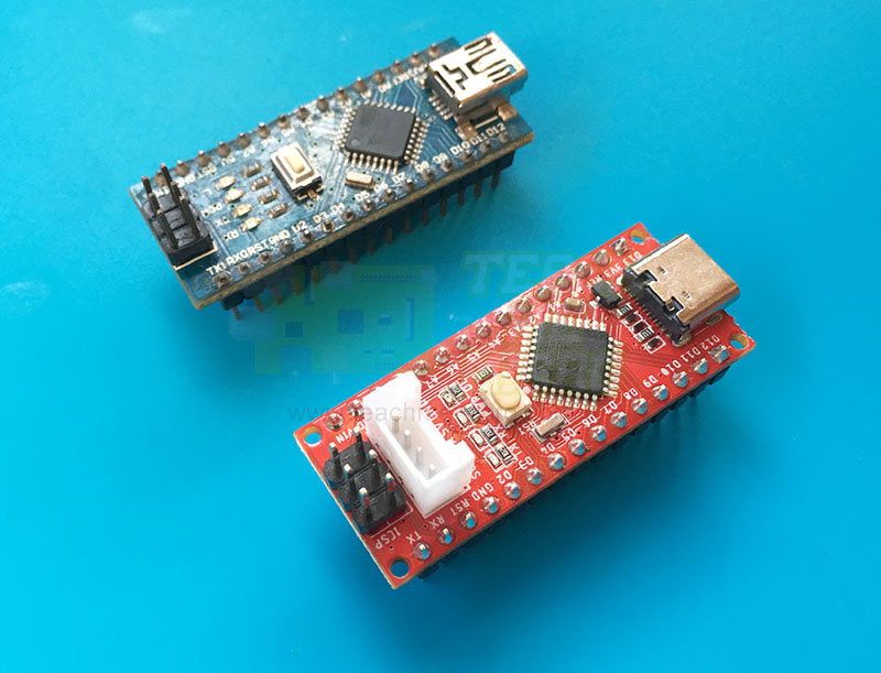
The Arduino Nano is a compact, breadboard-friendly ATmega328P development board with 14 digital I/O pins, eight analog inputs, six PWM outputs, and hardware support for UART, I2C, and SPI. This guide provides a complete Arduino Nano pinout, including GPIO functions, communication pins, power connections, and the ATmega328P port mapping.
You’ll also find the Arduino Nano schematic and circuit diagram later in this guide, which is useful when troubleshooting the board, tracing power connections, or designing hardware around the Nano.
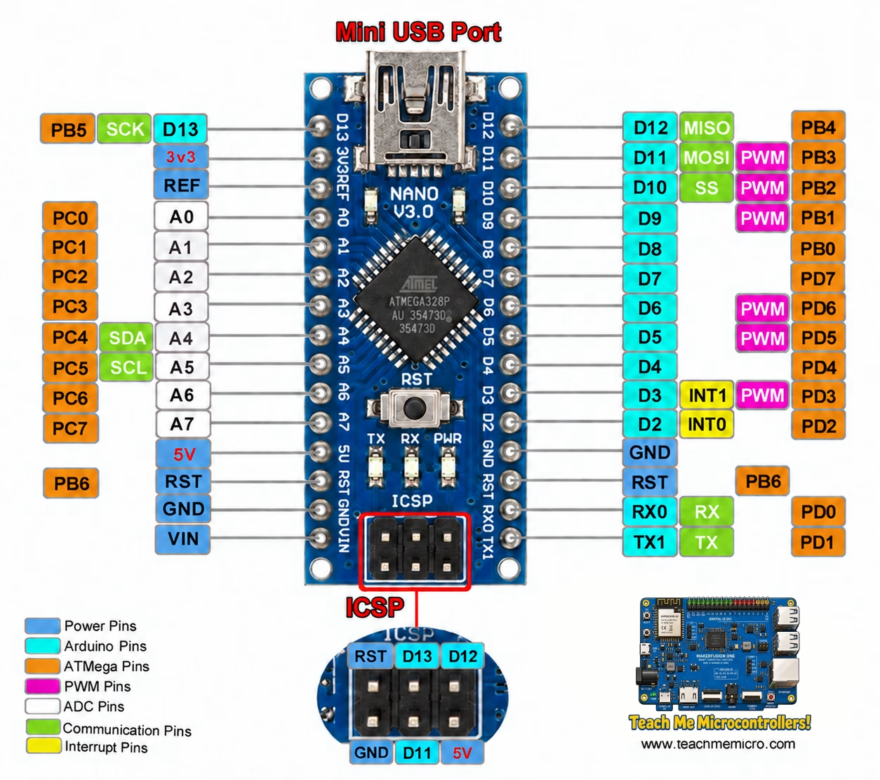
The diagram below shows the Arduino Nano V3 pinout. The board uses the ATmega328P, so many of its pin functions are similar to the Arduino Uno. However, the Nano also exposes A6 and A7, giving it eight analog inputs instead of six.
Interactive Arduino Nano Pinout Diagram
Arduino Nano Pins for Common Projects
Most Arduino Nano pins can be used as general-purpose I/O, but some have dedicated functions that can interfere with programming, serial communication, timers, or onboard hardware. For a simple project, D2 through D9 are usually the easiest digital pins to work with.
For most beginner projects, the safest general-purpose pins are:
| Use Case | Recommended Pins | Avoid / Be Careful |
|---|---|---|
| Digital input/output | D2–D9 | D0/D1 if using Serial |
| PWM output | D3, D5, D6, D9, D10, D11 | |
| I2C modules | A4 SDA, A5 SCL | Needs pullups on many modules |
| SPI modules | D10–D13 or ICSP header | D13 also controls built-in LED |
| Analog sensors | A0–A5 | A6/A7 are analog-input only |
| External interrupts | D2, D3 | D2 has INT0, D3 has INT1 |
Arduino Nano Pinout Description
The Arduino Nano pins are divided into digital pins, analog pins, power pins, and communication pins. Like the Arduino Uno, the Nano uses the ATmega328P microcontroller, but it includes two extra analog input pins: A6 and A7. Several pins also have alternate functions such as PWM, UART, I2C, SPI, and external interrupts.
Digital Pins
| Nano Pin | ATmega328P Port | Functions | Notes |
|---|---|---|---|
| D0 | PD0 | RX, UART | Used for serial upload/USB communication |
| D1 | PD1 | TX, UART | Used for serial upload/USB communication |
| D2 | PD2 | INT0 | External interrupt |
| D3 | PD3 | PWM, INT1 | PWM pin |
| D4 | PD4 | Digital I/O | General purpose |
| D5 | PD5 | PWM | Timer0 PWM |
| D6 | PD6 | PWM | Timer0 PWM |
| D7 | PD7 | Digital I/O | General purpose |
| D8 | PB0 | Digital I/O | General purpose |
| D9 | PB1 | PWM | Timer1 PWM |
| D10 | PB2 | PWM, SS | SPI chip select |
| D11 | PB3 | PWM, MOSI/COPI | SPI data out |
| D12 | PB4 | MISO/CIPO | SPI data in |
| D13 | PB5 | SCK, LED_BUILTIN | On-board LED |
Analog Pins
| Nano Pin | ATmega328P Port | Functions | Notes |
|---|---|---|---|
| A0 | PC0 | ADC0, Digital I/O | Analog input or digital pin |
| A1 | PC1 | ADC1, Digital I/O | Analog input or digital pin |
| A2 | PC2 | ADC2, Digital I/O | Analog input or digital pin |
| A3 | PC3 | ADC3, Digital I/O | Analog input or digital pin |
| A4 | PC4 | ADC4, SDA | I2C data pin |
| A5 | PC5 | ADC5, SCL | I2C clock pin |
| A6 | ADC6 | Analog input only | Cannot be used as digital I/O |
| A7 | ADC7 | Analog input only | Cannot be used as digital I/O |
Power Pins
| Pin | Function | Notes |
|---|---|---|
| VIN | External input voltage | Typically used with 7–12V input |
| 5V | Regulated 5V | Can power 5V modules if current is within limits |
| 3.3V | 3.3V output | Limited current output |
| GND | Ground | Common reference for circuits |
| RESET | Reset pin | Pull LOW to reset the board |
| AREF | Analog reference | Optional external reference for ADC |
Also, notice that the ATMega pins for each Arduino pin are also provided in the pinout diagram above. For details on how to use these pins, see Arduino Port Manipulation.
Arduino Nano Digital Pins
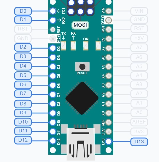
The Arduino Nano provides 14 digital pins, D0 through D13, operating at 5 V logic. D2 through D13 can generally be used as ordinary digital inputs or outputs, while D0 and D1 are shared with the hardware UART used for serial communication and sketch uploads. If your project uses the Serial Monitor, it is usually better to leave D0 and D1 free.
Arduino Nano PWM Pins
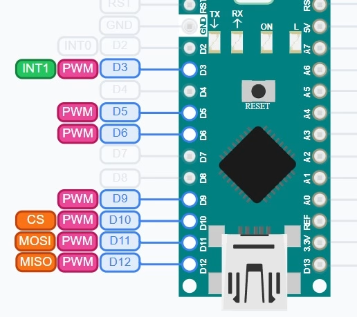
The Arduino Nano has six PWM-capable pins: D3, D5, D6, D9, D10, and D11. These are marked with a ~ symbol on most Nano boards. Arduino's analogWrite() function can generate PWM on these pins for tasks such as LED brightness control and DC motor speed control. PWM does not produce a true analog voltage; instead, it rapidly switches the output between HIGH and LOW.
Arduino Nano Analog Pins
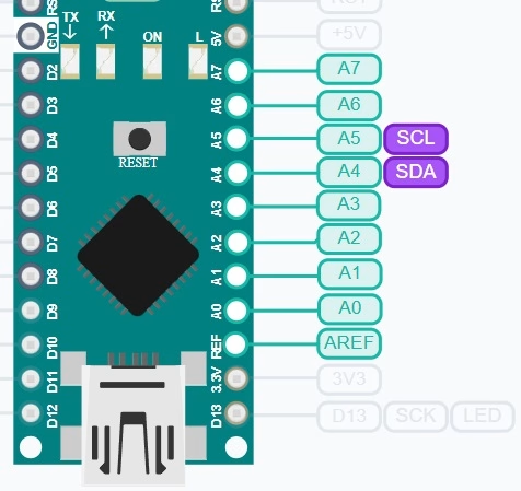
The Nano exposes eight analog inputs, A0 through A7. A0 through A5 can also operate as digital GPIOs, while A6 and A7 are analog-input only. The ATmega328P uses a 10-bit ADC, so analogRead() normally returns values from 0 to 1023.
Arduino Nano Power Pins
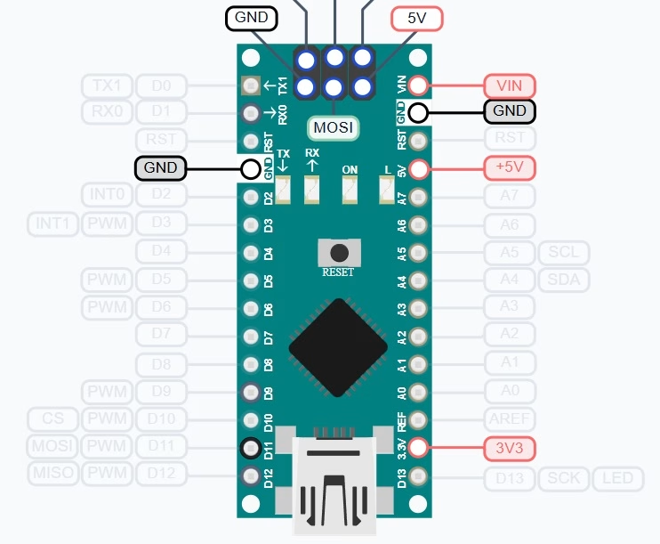
The Arduino Nano can be powered through the USB port, the VIN pin, or the 5V pin. For most projects, USB is the safest option during development. The VIN pin is used when supplying an external voltage, while the 5V and 3.3V pins can power small external modules if their current requirements are within the board’s limits.
Arduino Nano I2C Pins
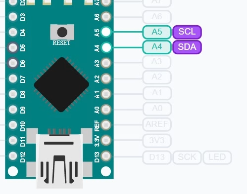
The Arduino Nano uses A4 for SDA and A5 for SCL. These pins connect directly to the ATmega328P's hardware I2C/TWI peripheral. Typical I2C devices include RTC modules, EEPROMs, OLED displays, and environmental sensors. Many breakout boards already include I2C pull-up resistors, so check the module before adding another pair.
Arduino Nano SPI Pins
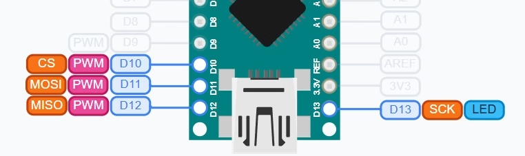
The hardware SPI interface uses D10 for SS, D11 for MOSI/COPI, D12 for MISO/CIPO, and D13 for SCK. The same SPI signals are also available through the six-pin ICSP header. D13 is additionally connected to the Nano's built-in LED, which can matter when that pin is used as a high-speed clock signal.
Arduino Nano UART Pins
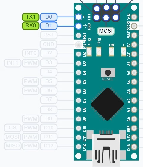
The Nano's hardware UART uses D0/RX and D1/TX. These pins are also for USB-to-serial communication on the classic Nano, so devices connected to them can interfere with sketch uploads or Serial Monitor communication.
Arduino Nano Schematic and Circuit Diagram
The Arduino Nano schematic shows how the board’s ATmega328P microcontroller connects to the USB interface, voltage regulator, reset circuit, LEDs, ICSP header, and external pins. It is especially useful when troubleshooting a Nano, tracing a damaged connection, or designing a circuit that connects directly to the board.

ATmega328P Microcontroller Circuit
At the center of the Arduino Nano schematic is the ATmega328P, the same 8-bit AVR microcontroller used on the classic Arduino Uno. It runs at 16 MHz and provides the Nano’s digital I/O, analog inputs, timers, PWM outputs, UART, SPI, and I2C interfaces.
The D0–D13 and A0–A7 pins on the Nano headers connect directly to ports on the ATmega328P. This is why the pinout table above also lists names such as PB3, PC4, and PD2. These are the AVR port names used with direct register access instead of Arduino functions such as digitalWrite().
The microcontroller uses a 16 MHz crystal oscillator, along with the associated capacitors, to provide its main system clock. The schematic also includes bypass capacitors close to the microcontroller supply pins to reduce noise on the 5 V rail.
USB-to-Serial Circuit
The classic Arduino Nano does not have native USB support in the ATmega328P. Instead, the official board uses an FT232RL USB-to-serial converter between the Mini-B USB connector and the ATmega328P UART pins.
When you upload a sketch or open the Arduino Serial Monitor, USB data is converted by the FT232RL into serial signals connected to D0/RX and D1/TX.
This also explains why connecting another device to D0 and D1 can sometimes cause upload or serial communication problems.
The FT232RL section also drives the RX and TX indicator LEDs, which flash when serial data moves between the computer and the Nano.
Arduino Nano Power Supply Circuit
The Nano can receive power from either USB or the VIN pin. In the official design, VIN passes through an LM1117 5 V linear regulator, while USB already supplies approximately 5 V. Arduino specifies VIN as a 7–12 V input range.
A diode in the power-selection section prevents the USB supply and externally regulated supply from feeding directly into each other. The resulting +5V rail powers the ATmega328P and most of the board circuitry.
The Nano also provides a 3.3 V output. On the classic official Nano, this supply comes from the FT232RL’s internal 3.3 V regulator rather than from a separate high-current regulator. Arduino’s current datasheet shows this 3.3 V rail as part of the FT232RL power path.
This distinction is important when powering external hardware: the 3.3 V pin is for relatively small loads rather than high-current 3.3 V modules.
Reset and Auto-Reset Circuit
The Nano’s RESET pin connects to the ATmega328P reset input. Pulling RESET low restarts the microcontroller.
The schematic also includes an automatic reset circuit connected to the USB-to-serial interface. When the Arduino IDE begins an upload, the serial interface briefly drives the reset line through a capacitor. This causes the bootloader to run so that a new sketch transfers without manually pressing the reset button.
This is why a Nano normally resets automatically when you click Upload in the Arduino IDE.
ICSP Header
The six-pin ICSP header exposes the ATmega328P’s SPI programming signals:
| ICSP Signal | Nano Pin |
|---|---|
| MOSI / COPI | D11 |
| MISO / CIPO | D12 |
| SCK | D13 |
| RESET | RESET |
| VCC | 5V |
| GND | GND |
The header can connect to an external AVR programmer to write firmware or restore the bootloader. Because MOSI, MISO, and SCK are the same hardware SPI signals used by D11, D12, and D13, the ICSP connector can also be useful when interfacing hardware that expects the standard Arduino ICSP pin layout.
LED Circuits
The classic Nano contains several onboard LEDs visible in the schematic:
- Power LED — indicates that the board is receiving power.
- RX LED — flashes on serial data receive over USB.
- TX LED — flashes on serial data transmit over USB.
- Built-in LED — connected to D13/SCK.
The D13 LED is worth remembering when using that pin for SPI or other applications because the onboard LED circuit remains connected to the signal.
How the Schematic Relates to the Nano Pinout
The pinout diagram tells you what each external Nano pin does, while the schematic shows what that pin connects to inside the board.
For example:
- A4 connects to the ATmega328P PC4/ADC4 pin and also serves as I2C SDA.
- A5 connects to PC5/ADC5 and serves as I2C SCL.
- D11–D13 connect to the AVR hardware SPI peripheral.
- D0 and D1 connect both to the ATmega328P UART and the USB-to-serial converter.
- VIN feeds the 5 V voltage regulator rather than connecting directly to the microcontroller.
- 5V connects directly to the regulated 5 V rail.
Looking at both diagrams together is therefore useful when troubleshooting a pin or when you need to understand why a particular pin behaves differently from an ordinary GPIO.
Arduino Nano vs Arduino Uno Pinout
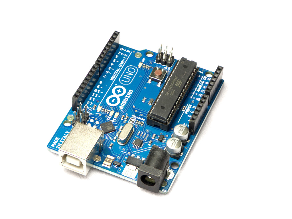
Because both boards use the ATmega328P, the Arduino Nano and Arduino Uno have nearly identical GPIO functions. A sketch written for the Uno will often work on a Nano without pin changes. The main pinout difference is that the Nano exposes two additional ADC inputs, A6 and A7.
| Feature | Arduino Nano | Arduino Uno |
|---|---|---|
| Microcontroller | ATmega328P | ATmega328P |
| Digital I/O | 14 | 14 |
| PWM Pins | 6 | 6 |
| Analog Inputs | 8 | 6 |
| USB Connector | Mini-B on classic Nano | USB-B on classic Uno |
| Breadboard Friendly | Yes | No |
Common Arduino Nano Pinout Mistakes
Using D0 and D1 for normal I/O
D0 and D1 connect to the hardware serial interface. If you connect sensors, relays, or modules to these pins, uploading sketches or using the Serial Monitor may fail.
Using A6 and A7 as digital pins
A6 and A7 are analog-input only. Use A0 to A5 if you need analog pins that can also work as digital I/O.
Forgetting that D13 is connected to the built-in LED
D13 is usable as a normal digital pin, but it also connects to the on-board LED.
Connecting I2C modules to the wrong pins
On the Arduino Nano, SDA is A4 and SCL is A5.
Supplying the wrong voltage to VIN or 5V
VIN and the 5V pin are not interchangeable. VIN feeds the board through its voltage regulator, while the 5V pin connects to the regulated 5 V rail. When powering the board externally, make sure you understand which input your supply should use before connecting it.
Arduino Nano Pinout Code Examples
Blink the Built-in LED on D13
void setup() {
  pinMode(13, OUTPUT);
}

void loop() {
  digitalWrite(13, HIGH);
  delay(500);
  digitalWrite(13, LOW);
  delay(500);
}
Read an Analog Sensor on A0
void setup() {
  Serial.begin(9600);
}

void loop() {
  int sensorValue = analogRead(A0);
  Serial.println(sensorValue);
  delay(500);
}
Generate PWM Output on D9
void setup() {
  pinMode(9, OUTPUT);
}

void loop() {
  analogWrite(9, 128); // about 50% duty cycle
}
Arduino Nano Pinout FAQ
What are the PWM pins on Arduino Nano?
The PWM pins are D3, D5, D6, D9, D10, and D11.
What are the I2C pins on Arduino Nano?
A4 is SDA and A5 is SCL.
What are the SPI pins on Arduino Nano?
D10 is SS, D11 is MOSI/COPI, D12 is MISO/CIPO, and D13 is SCK. These signals are also available on the ICSP header.
Can A6 and A7 be used as digital pins?
No. A6 and A7 are analog-input only on the Arduino Nano.
What voltage does the Arduino Nano use?
The Nano uses 5V logic. VIN accepts 7–12V input according to the official Arduino pinout.