
Introduction
A 16x2 monochrome LCD module is a widely used display in microcontroller projects. It can show two lines of text, each up to 16 characters long, making it ideal for simple user interfaces. These LCDs are based on the HD44780 controller (or compatible), which accepts commands and data via an 8-bit or 4-bit parallel interface.
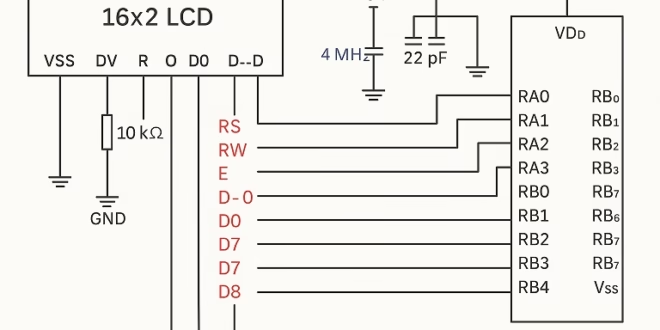
The LCD works by receiving control signals (RS, R/W, E) and data signals (D0–D7 or D4–D7 for 4-bit mode). In this tutorial, we’ll use 8-bit mode for simplicity. The PIC16F84A will send initialization commands to the LCD, followed by ASCII characters to be displayed.
Understanding the control lines:
- RS (Register Select):
- 0 = Instruction/command (e.g., clear display).
- 1 = Data (character to display).
- R/W (Read/Write):
- 0 = Write to LCD.
- 1 = Read from LCD (rarely needed, we’ll keep it 0.
- E (Enable):
- A high-to-low pulse latches the data/command into the LCD.
Once initialized, the LCD can display text by sending ASCII codes as data.
Materials
- PIC16F84A microcontroller
- 16x2 HD44780-based monochrome LCD module
- 4 MHz crystal oscillator + 2 × 22pF capacitors
- 10kΩ potentiometer (for LCD contrast adjustment)
- Breadboard and jumper wires
- 5V regulated power supply
Code (Assembly for PIC16F84A)
We’ll walk through the full code, then explain each part.
Full Program
;===========================================================
; Program: LCD 16x2 Display with PIC16F84A
;===========================================================

    list p=16F84A
    include <p16f84a.inc>

    __CONFIG _FOSC_HS & _WDTE_OFF & _PWRTE_ON & _CP_OFF

;-------------------------------
; Pin connections
; LCD Data -> PORTB
; RS -> RA0
; RW -> RA1 (tied low, write only)
; EN -> RA2
;-------------------------------

    cblock 0x20
        temp
    endc

;-------------------------------
; Reset vector
;-------------------------------
    org 0x00
    goto main

;-------------------------------
; Subroutines
;-------------------------------
delay_ms
    movlw   d'250'
    movwf   temp
d1  nop
    nop
    decfsz  temp, f
    goto d1
    return

lcd_pulse
    bsf     PORTA,2      ; E=1
    call    delay_ms
    bcf     PORTA,2      ; E=0
    call    delay_ms
    return

lcd_cmd
    bcf     PORTA,0      ; RS=0
    movwf   PORTB        ; Send command
    call    lcd_pulse
    return

lcd_data
    bsf     PORTA,0      ; RS=1
    movwf   PORTB        ; Send data
    call    lcd_pulse
    return

lcd_init
    ; Function Set: 8-bit, 2 line, 5x8 font
    movlw   0x38
    call    lcd_cmd

    ; Display ON, Cursor OFF
    movlw   0x0C
    call    lcd_cmd

    ; Clear display
    movlw   0x01
    call    lcd_cmd

    ; Entry mode: auto-increment
    movlw   0x06
    call    lcd_cmd
    return

;-------------------------------
; Main Program
;-------------------------------
main
    bsf     STATUS, RP0
    movlw   0x00
    movwf   TRISB       ; PORTB = output
    movlw   0xF8
    movwf   TRISA       ; RA0-RA2 output, RA3-RA4 input
    bcf     STATUS, RP0

    call    lcd_init

    ; Write "HELLO"
    movlw   'H'
    call    lcd_data
    movlw   'E'
    call    lcd_data
    movlw   'L'
    call    lcd_data
    movlw   'L'
    call    lcd_data
    movlw   'O'
    call    lcd_data

endless
    goto endless

    end
![]() Simulate this code in PICSimulator
Simulate this code in PICSimulator
Code Explanation
1. Configuration and Setup
- Sets processor type and includes the register definitions.
- Configures the microcontroller for High-Speed crystal oscillator, watchdog timer off, power-up timer on, and code protection off.
2. LCD Pin Mapping
- PORTB is used for LCD data (D0–D7).
- RA0 = RS, RA1 = R/W (grounded), RA2 = E.
- Only writing to the LCD is needed, so R/W is tied to ground.
3. Delay Routine
A simple software delay loop to let the LCD process commands.
4. LCD Enable Pulse
The LCD latches commands/data on the falling edge of E.
5. Sending Commands and Data
These subroutines separate instructions (clear, cursor) from characters (ASCII).
6. LCD Initialization
These commands are required at startup to prepare the LCD.
7. Writing Text
Each ASCII character is written sequentially to the LCD.
Conclusion
In this tutorial, we connected a 16x2 monochrome LCD to a PIC16F84A microcontroller using an 8-bit parallel interface. We wrote initialization and display routines in assembly, giving full control of the LCD at a low level.
This project demonstrates how to:
- Initialize the LCD in 8-bit mode.
- Send commands and data separately.
- Display custom strings of text.
With this foundation, you can extend the program to display sensor data, menu options, or real-time feedback for embedded projects.


")

