
The RP2040-Zero from Waveshare is one of those boards that looks too small at first glance, but is actually a very capable microcontroller board. It is based on the same RP2040 chip used in the Raspberry Pi Pico, but Waveshare placed it on a much smaller board with a USB-C connector, castellated edges, reset and boot buttons, and an onboard RGB LED.
I like boards like this for compact projects. If a Raspberry Pi Pico feels too long for your enclosure or breadboard layout, the RP2040-Zero is a nice alternative. The tradeoff is that the pin labels are tighter, some pins are on small pads, and the onboard LED is not a normal single-color LED. But once you know those details, it is quite easy to use.
In this tutorial, we will look at the RP2040-Zero features, pinout, Arduino IDE setup, boot mode, and a simple RGB LED blink program.
RP2040-Zero Features
The RP2040-Zero uses the RP2040 microcontroller, which has a dual-core Arm Cortex-M0+ processor running up to 133 MHz and 264 kB of SRAM. Waveshare’s RP2040-Zero board adds 2 MB of onboard flash, USB-C, castellated edges, and brings out 29 GPIO pins, although only some are available through the main pin headers.
Here are the main features:
| Feature | Details |
|---|---|
| Microcontroller | RP2040 |
| CPU | Dual-core Arm Cortex-M0+ |
| Clock Speed | Up to 133 MHz |
| SRAM | 264 KB |
| Flash | 2 MB onboard flash |
| USB | USB-C, USB 1.1 device/host support |
| GPIO | 29 GPIO pins total |
| ADC | 4 × 12-bit ADC inputs |
| PWM | 16 PWM channels |
| Communication | 2 × UART, 2 × SPI, 2 × I2C |
| Extra feature | Onboard WS2812B RGB LED |
| Programming | USB drag-and-drop / Arduino IDE / MicroPython / C/C++ |
The RP2040 also includes PIO, or Programmable I/O, which is one of the best features of this chip. PIO lets the chip handle special timing-heavy tasks such as custom serial protocols, LED driving, or unusual communication signals without forcing the CPU to bit-bang everything. Raspberry Pi lists 8 PIO state machines on the RP2040.
RP2040-Zero vs Raspberry Pi Pico
The easiest way to understand the RP2040-Zero is to think of it as a smaller Pico-like board.
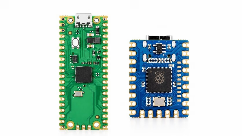
The Raspberry Pi Pico is easier to handle on a breadboard because it has a wider and longer layout. The RP2040-Zero is more compact, so it is better for small projects, wearables, custom PCBs, keyboards, USB devices, and projects where space matters.
The RP2040-Zero also uses USB-C, which is convenient because most newer cables and chargers already use it. Just make sure you use a data-capable USB-C cable, not a charge-only cable. A charge-only cable is one of the most common reasons the board powers up but does not appear in the Arduino IDE.
RP2040-Zero Pinout Overview
The RP2040-Zero exposes GPIO pins along the edge headers and extra pads. On the main 23-pin header, you get GPIO0 to GPIO15, GPIO26 to GPIO29, 3V3, GND, and VSYS. Two smaller 5-pin headers expose GPIO17 to GPIO21, and GPIO22 to GPIO25 plus GND. The schematic also shows the onboard WS2812B RGB LED connected to GPIO16.
Here is a simplified pin list:
| Pin / GPIO | Common Use |
|---|---|
| GPIO0 to GPIO15 | Digital I/O, PWM, UART, SPI, I2C depending on configuration |
| GPIO16 | Onboard WS2812B RGB LED |
| GPIO17 to GPIO25 | Digital I/O and peripheral functions |
| GPIO26 / ADC0 | Analog input |
| GPIO27 / ADC1 | Analog input |
| GPIO28 / ADC2 | Analog input |
| GPIO29 / ADC3 | Analog input |
| 3V3 | 3.3V output from onboard regulator |
| GND | Ground |
| VSYS | Main supply rail / USB-related supply path |
One important thing to remember is that RP2040 GPIO pins are 3.3V logic pins. Do not connect a 5V signal directly to a GPIO pin. If you are working with 5V modules, use a level shifter or check if the module’s output is already 3.3V-safe.
Powering the RP2040-Zero
The easiest way to power the RP2040-Zero is through the USB-C connector. For most beginner projects, this is what I recommend.
You can also power the board through its power pins, but be careful. Waveshare notes that the board does not include battery protection, and if you power it from a battery you must handle charging, over-discharge protection, and backflow protection yourself.
For a first test, use USB-C. It removes many possible mistakes.
Setting Up Arduino IDE for RP2040-Zero
The RP2040-Zero can be programmed in different ways, including MicroPython, C/C++, and Arduino IDE. For this guide, we will use the Arduino IDE because it is usually the fastest way to test the board.
The Arduino support we will use is the Arduino-Pico core by Earle Philhower. Its official installation instructions say to add the RP2040 package URL in Arduino IDE Preferences, then install the board package from Boards Manager.
Step 1: Install Arduino IDE
Download and install the latest Arduino IDE from the Arduino website.
Step 2: Add the RP2040 Board Manager URL
Open Arduino IDE, then go to:
File > Preferences
In Additional Boards Manager URLs, add this URL:
https://github.com/earlephilhower/arduino-pico/releases/download/global/package_rp2040_index.json
If you already have another URL there, such as the ESP32 board URL, separate the URLs with a comma.
Step 3: Install the RP2040 Board Package
Go to:
Tools > Board > Boards Manager
Search for:
pico
Install:
Raspberry Pi Pico/RP2040 by Earle F. Philhower, III
Step 4: Select the Board
After installation, go to:
Tools > Board > Raspberry Pi RP2040 Boards
Select the RP2040-Zero/Waveshare RP2040-Zero option if it appears in your installed version. If your Arduino-Pico version does not show a specific RP2040-Zero option, you can use a generic RP2040 or Raspberry Pi Pico selection for simple tests, but the dedicated board entry is preferred when available.
Entering Boot Mode
For the first upload, you may need to put the board into bootloader mode manually.
There are two common ways to do it.
If the board is unplugged:
-
- Hold the BOOT button.
- Plug the USB-C cable into your computer.
- Release the BOOT button.
- A drive named something like RPI-RP2 should appear.
If the board is already plugged in:
-
- Press and hold RESET.
- Press and hold BOOT.
- Release RESET first.
- Release BOOT.
- The board should enter flashing mode.
Waveshare’s FAQ gives the same reset-and-boot sequence for flashing firmware.
First Arduino Program: Blink the Onboard RGB LED
On many Arduino boards, the first test is usually the standard Blink sketch. The RP2040-Zero is a little different because its onboard LED is not a normal LED connected directly to a GPIO pin.
The onboard LED is a WS2812B RGB LED, so it needs a NeoPixel-style signal. According to the RP2040-Zero schematic, the RGB LED data pin is connected to GPIO16.
Before uploading the code, install the Adafruit NeoPixel library:
Sketch > Include Library > Manage Libraries
Search for:
Adafruit NeoPixel
Install it, then upload this sketch:
#include <Adafruit_NeoPixel.h>

#define RGB_LED_PIN 16
#define NUM_LEDS 1

Adafruit_NeoPixel pixel(NUM_LEDS, RGB_LED_PIN, NEO_GRB + NEO_KHZ800);

void setup() {
  pixel.begin();
  pixel.setBrightness(30);  // Keep it low so it is not too bright
  pixel.clear();
  pixel.show();
}

void loop() {
  // Red
  pixel.setPixelColor(0, pixel.Color(255, 0, 0));
  pixel.show();
  delay(500);

  // Green
  pixel.setPixelColor(0, pixel.Color(0, 255, 0));
  pixel.show();
  delay(500);

  // Blue
  pixel.setPixelColor(0, pixel.Color(0, 0, 255));
  pixel.show();
  delay(500);

  // Off
  pixel.clear();
  pixel.show();
  delay(500);
}
After uploading, the onboard RGB LED should cycle through red, green, blue, then turn off.
If you uploaded the ordinary Arduino Blink example and nothing happened, the board is probably fine. The issue is just that the onboard LED is not a simple LED. You need the WS2812/NeoPixel code above.
Testing a Normal GPIO Pin
After testing the onboard RGB LED, it is also a good idea to test a normal GPIO pin with an external LED. This confirms that the board pins work as expected.
Connect:
| RP2040-Zero Pin | Component |
|---|---|
| GPIO0 | 220Ω resistor |
| Resistor other end | LED anode |
| LED cathode | GND |
Then upload this sketch:
#define LED_PIN 0

void setup() {
  pinMode(LED_PIN, OUTPUT);
}

void loop() {
  digitalWrite(LED_PIN, HIGH);
  delay(500);

  digitalWrite(LED_PIN, LOW);
  delay(500);
}
This time we are using a normal LED, so the usual digitalWrite() method works.
Reading an Analog Input
The RP2040-Zero also has analog-capable pins. GPIO26, GPIO27, GPIO28, and GPIO29 can be used as ADC inputs. Waveshare lists 4 × 12-bit ADC channels for the board, and the schematic labels GPIO26 to GPIO29 as ADC0 to ADC3.
For example, connect a potentiometer like this:
| Potentiometer Pin | RP2040-Zero Pin |
|---|---|
| One side | 3V3 |
| Middle pin | GPIO26 / ADC0 |
| Other side | GND |
Then upload this sketch:
#define POT_PIN 26

void setup() {
  Serial.begin(115200);
}

void loop() {
  int value = analogRead(POT_PIN);

  Serial.print("ADC value: ");
  Serial.println(value);

  delay(300);
}
Open the Serial Monitor at 115200 baud and turn the potentiometer. You should see the ADC value change.
Common Problems and Fixes
The board powers on but does not appear in Arduino IDE
Use a different USB-C cable. Many USB-C cables are charge-only and cannot transfer data.
The first upload does not work
Manually enter boot mode by holding BOOT while plugging in the board. After the first successful upload, the Arduino-Pico core usually handles reset automatically, but if the board hangs, you may need to enter boot mode manually again.
The onboard LED does not blink with the normal Blink sketch
That is expected. The onboard LED is a WS2812B RGB LED on GPIO16, not a simple LED. Use the NeoPixel example above.
I cannot debug with SWD
Waveshare notes that the RP2040-Zero does not expose the SWD debugging pins. If you need proper SWD debugging, a Raspberry Pi Pico or another RP2040 board with debug pins is easier to use.
Final Thoughts
The RP2040-Zero is a small but powerful board. For beginners, the only slightly confusing part is the onboard RGB LED because it does not behave like a normal Arduino LED. Once you know that it uses GPIO16 and needs WS2812/NeoPixel-style control, the board becomes much easier to test.
For compact projects, USB devices, small sensor boards, tiny displays, custom PCBs, or keyboard-style projects, the RP2040-Zero is a very useful alternative to the Raspberry Pi Pico. It gives you the same RP2040 core in a smaller layout, and the USB-C connector is a nice bonus.


