
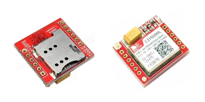
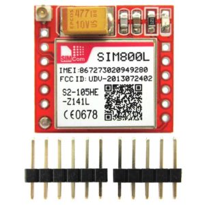
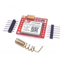
The SIM800L is a small, low-cost GSM/GPRS module (2G) with most of the features of larger SIM900 shields. In this Arduino SIM800L tutorial, you’ll wire the module safely, send/receive SMS, and make HTTP requests over GPRS — plus fix the most common power and network issues.
Video Tutorial
What is SIM800L?
- SIM800L is a quad-band GSM/GPRS module (850/900/1800/1900 MHz) that supports:
- Voice calls (speaker/mic pins)
- SMS send/receive
- GPRS data (HTTP/TCP/UDP)
- FM radio
- AT commands (UART)
Read more information from the SIM800L Datasheet.
If you own a SIM900 shield instead, see: SIM900 Tutorial
Powering the Board
- Voltage: 3.7–4.2 V (typical 4.0 V). Do not power from Arduino 5 V or 3.3 V pins.
- Current: Up to 2 A bursts during transmit. Your supply must handle this.
- Recommended supplies:
- 1-cell Li-Po (3.7 V nominal) OR
- A buck regulator module (e.g. LM2596S) set to ~4.0 V.
- Decoupling: Place 100 µF + 1000 µF low-ESR capacitors near the module Vcc/GND.
- Wiring: Keep power leads short and thick; share common GND with Arduino.
Power requirements is probably the most common issue with the SIM800L. This board draws a maximum of 2 A with an input voltage of 3.7 V to 4.2 V. This means you must not connect its pins directly to a 5 V Arduino! It doesn't even run on 3.3 V. However, its TX and RX pins are 5V tolerant.
Some YouTube videos power their modules from the Arduino UNO's power pins which really doesn't work for me. When on USB port, the Arduino's 5V pin can supply a maximum of 450 mA and when on its DC Jack, about 800 mA. However, these might explain why their modules work:
- their Arduino's have internal regulators that drop the voltage to ~4.4-4.5 V when the SIM800L is connected
- they are very close to mobile network transmitters, which means the SIM800L doesn't need to draw too much power to establish a connection
Some also use a diode to drop the 5 V voltage to ~4.3 V (assuming a silicon diode). Maybe this would solve the voltage problem, but not the current problem.
The better approach is either to use a regulator or just have the SIM800L draw from a Li-Po battery.
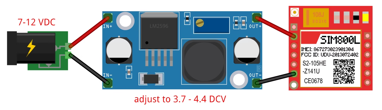
If selecting a voltage regulator, I recommend the LM2596S regulator module.
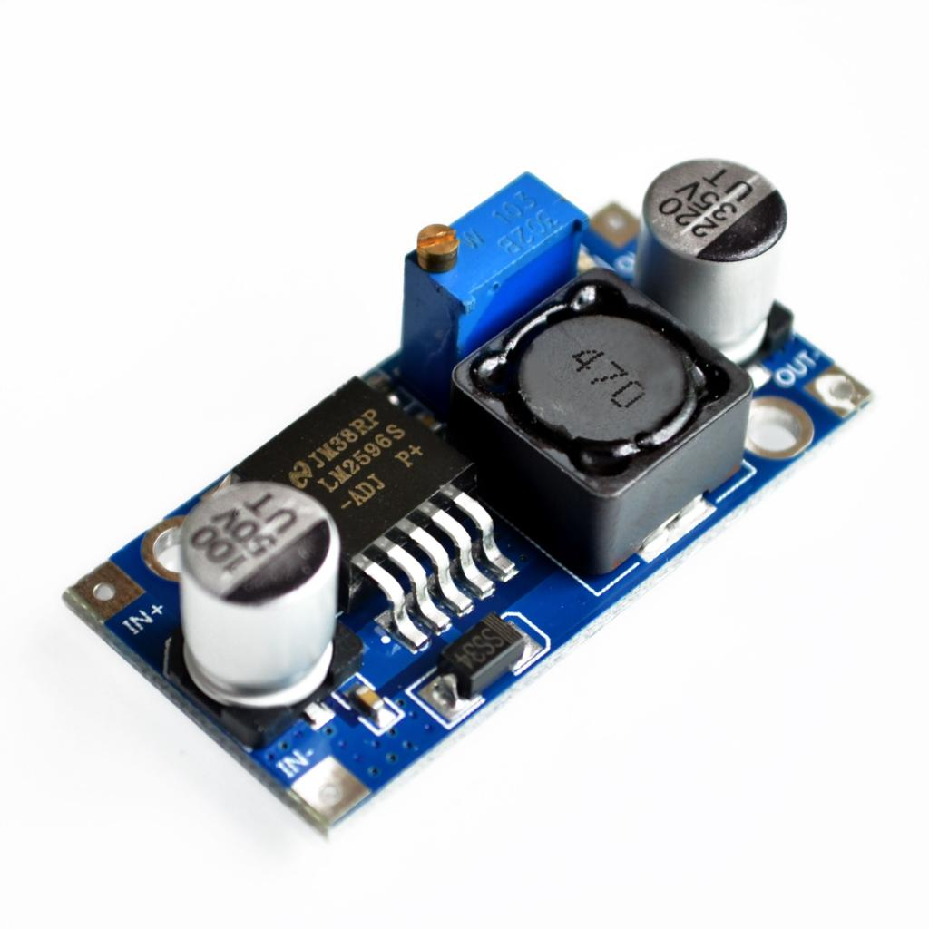
The LM2596S can provide a maximum 3 A to its load. You simply use a higher voltage in its input then adjust the on-board potentiometer to have 3.7 to 4.4 V for the SIM800L. Take note that the input voltage must be at least 1.5 V higher than the output.
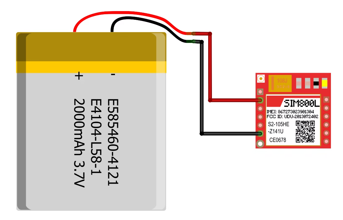
A Li-Po battery works well too, since they provide 3.7 V. I recommend Li-Po battery with higher ampere-hour ratings so that it can provide the SIM800L's current requirements. My network test project uses a battery to supply power to the SIM800L.
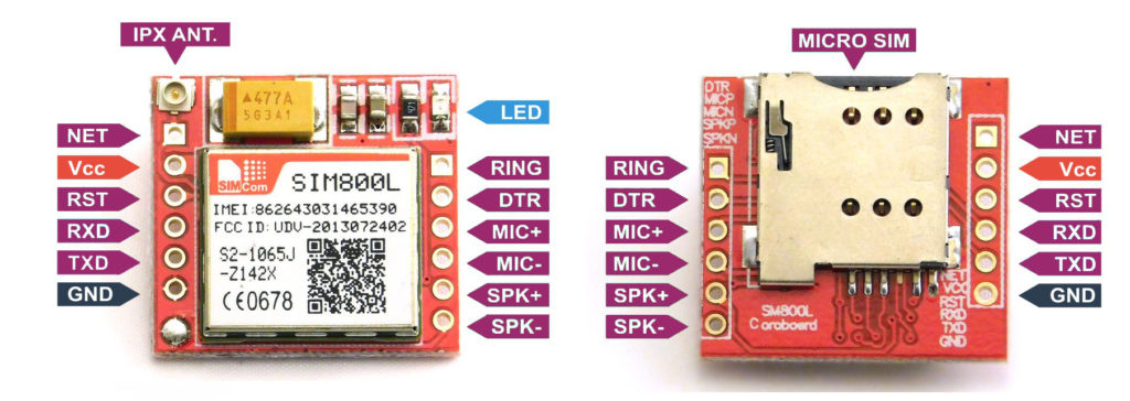
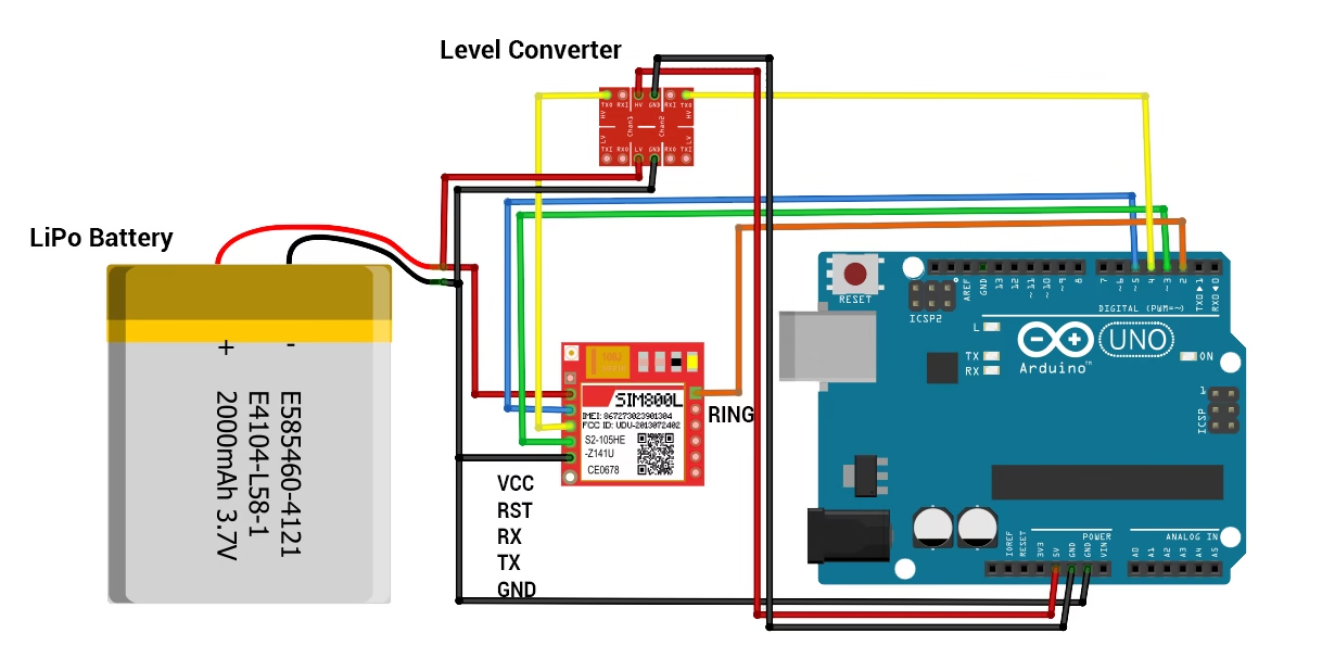
Wiring & Level Shifting
SIM800L’s UART is 3.3 V tolerant on RXD; many boards survive 5 V UART, but safest is level shifting from Arduino TX → SIM800L RXD.
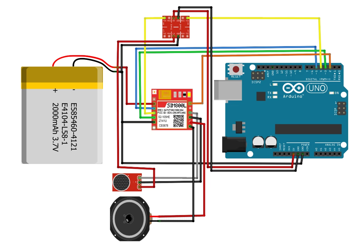
Typical connections (Arduino UNO):
| SIM800L | Description | Arduino |
|---|---|---|
| Vcc | 3.7–4.2 V supply (cap nearby) | External supply (NOT 5 V pin) |
| GND | Ground | GND (common with Arduino) |
| TXD | SIM800L TX | Arduino RX (e.g., D3) |
| RXD | SIM800L RX | Arduino TX via level shifter (e.g., D4) |
| RST | Reset (optional) | Any digital (e.g., D5) |
| RING | Ring indicator (optional) | D2 if using interrupt on incoming call |
Baud: 9600 is safe for SoftwareSerial. For boards with extra hardware UART (Mega/Leonardo/ESP32), prefer hardware serial.
Connecting the SIM800L to Network
If the power to the SIM800L is enough, the on-board LED starts blinking. If there's not enough power, the LED blinks for about three seconds, then turns off.
The frequency of the blinking means something:
Blink every 1s: searching for network

Blink every 3s: registered on network
Blink ~2×/s: GPRS active

Here's a video showing these LED indications:
Antennas are essential for this kind of module especially if your project is indoors. Without an antenna, there would not be enough transmitting power for the SIM800L to perform GSM services such as calls and SMS.
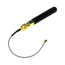
The image above is an outdoor whip antenna and I found this antenna to be more effective than the indoor helical antenna that comes with the SIM800L module:
Another type of antenna is the PCB antenna:
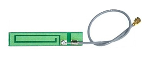
This type of antenna is cheaper and doesn't take much space as that of the whip antenna. Performance wise, the PCB antenna can be as good as the whip if the design is correct.
My recommendation is to use both the indoor helical antenna and either the whip or PCB antenna.
If you are still having trouble with the SIM800L, I suggest you try out my network test project. This helps you test out if the module is really connecting to a network or is getting enough power.
SIM800L and AT Commands
You can control SIM800L using AT commands over serial. Here are some of the basic commands.
| Command | Purpose | Expected Reply |
|---|---|---|
| AT | Handshake | OK |
| AT+CPIN? | SIM ready? | +CPIN: READY |
| AT+CSQ | Signal quality | +CSQ: <rssi>,<ber> (31 = best RSSI) |
| AT+CREG? | Network registration | +CREG: 1,1 (home) / 1,5 (roaming) |
| AT+CGATT? | GPRS attached? | +CGATT: 1 |
| AT+SAPBR | Bearer profile (APN) | OK |
| AT+HTTPINIT/HTTPPARA/HTTPACTION | HTTP ops | status codes |
The Arduino sends these commands serially to the SIM800L, and the latter replies via the same serial port.
The first command is the initial handshake command, which is simply:
AT
If the SIM800L is good to go, it should reply with:
OK
Other commands we can use to check the SIM800L is the signal quality test:
AT+CSQ
for which the module should reply something like this:
+CSQ:18,99
The first number is the Received Signal Strength Indicator (RSSI) which tells you about the network signal the module is receiving. A good RSSI is 31:
0 -> -113 dBm or less
1 -> -111 dBm
2...30 -> -109...-53 dBm
31 -> -51 dBm or greater
99 -> not known or not detectable
The second number is the Bit Error Rate (BER) which is the number of bit errors divided by the total number of bits received by the module. Possible values are 0 to 7 or 99:
0 -> BER < 0.2%
1 -> 0.2% < BER < 0.4%
2 -> 0.4% < BER < 0.8%
3 -> 0.8% < BER < 1.6%
4 -> 1.6% < BER < 3.2 %
5 -> 3.2% < BER < 6.4%
6 -> 6.4% < BER < 12.8%
7 -> 12.8% < BER 99 -> not known or not detectable
The higher the BER, the more bit errors. Thus, the ideal BER value should be closer to 0.
The network registration test can tell you if the SIM800L is ready to send/receive SMS or make calls:
AT+CREG?
The module will reply with two numbers:
+CREG: 1,1
Where the 1st number is:
0 not registered, MT is not currently searching a new operator to register to
1 registered, home network
2 not registered, but MT is currently searching a new operator to register to
3 registration denied
4 unknown (e.g. out of GERAN/UTRAN/E-UTRAN coverage)
5 registered, roaming
6 registered for "SMS only", home network (applicable only when indicates E-UTRAN)
7 registered for "SMS only", roaming (applicable only when indicates E-UTRAN)
8 attached for emergency bearer services only (see NOTE 2) (not applicable)
9 registered for "CSFB not preferred", home network (applicable only when indicates E-UTRAN)
10 registered for "CSFB not preferred", roaming (applicable only when indicates E-UTRAN)
and the second number is:
0 GSM
1 GSM Compact
2 UTRAN
3 GSM w/EGPRS
4 UTRAN w/HSDPA
5 UTRAN w/HSUPA
6 UTRAN w/HSDPA and HSUPA
7 E-UTRAN
The ideal reply from a SIM800L to function well (including data) is:
+CREG: 1,3
+CREG: 1,4
+CREG: 1,5
+CREG: 1,6
Note that results may vary with your location.
The Arduino UNO has a hardware serial port but it's the one used for sending code to it via USB. Instead, we use a serial port emulated through software. For this example, use the provided wiring diagram in the previous section.
First we include the library and then create a Software Serial object:
#include <SoftwareSerial.h>

SoftwareSerial sim800l(3, 2);
We need to know the reply of the SIM800L. So we initialize both hardware and serial ports in order to print the replies via serial monitor:
Serial.begin(9600);
sim800l.begin(9600);
To send a command, we do:
sim800l.println("AT");
Or we can just send the commands via serial monitor. To do that and also read the reply from the SIM800L, we place this inside loop():
while (Serial.available()){
   delay(1);
   sim800l.write(Serial.read());
}

while (sim800l.available()){
   Serial.write(sim800l.read());
}
Here is the full sketch for the AT command test:
#include <SoftwareSerial.h>

SoftwareSerial sim800l(3,2);

void setup(){
  Serial.begin(9600);
  sim800l.begin(9600);
}

void loop(){
  while (Serial.available()){
    delay(1);
    sim800l.write(Serial.read());
  }

  while (sim800l.available()){
    Serial.write(sim800l.read());
  }
}
Open Serial Monitor @ 9600, type AT, expect OK. Then try AT+CSQ, AT+CREG?.
Here's how the SIM800L is responding with AT Commands:
The FONA Library
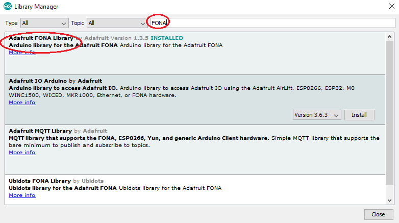
While we can maximize the functions of the SIM800l through AT commands, it is much easier to use an existing library instead. The library I recommend is Adafruit's FONA library. Download it here and extract it on Documents > Arduino > libraries. Or you can go to Sketch > Include Library > Manage Libraries and type "FONA" in the search bar.
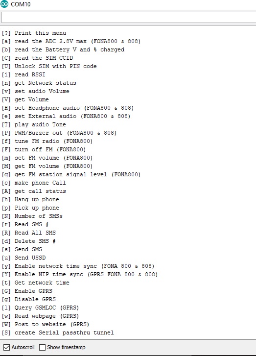
The library comes with a number of examples. The FONA_test sketch gives us access to all the SIM800l functions! If you upload the sketch and use the same wiring diagram, you'll see this on the serial monitor:
Here's a short video showing how I sent an SMS using this library:
SMS Sending
The FONA library has a simple sendSMS() function that accepts the number and message as parameters and returns true if the message was sent through the network successfully. Here's an example code that sends one SMS:
#include <SoftwareSerial.h>
#include "Adafruit_FONA.h"

#define FONA_RX 2
#define FONA_TX 3
#define FONA_RST 4

char replybuffer[255];

SoftwareSerial sim800l = SoftwareSerial(FONA_TX, FONA_RX);

Adafruit_FONA gsm = Adafruit_FONA(FONA_RST);

//uint8_t readline(char *buff, uint8_t maxbuff, uint16_t timeout = 0);

void setup() {
  Serial.begin(9600);
  sim800l.begin(9600);
  if (! gsm.begin(sim800l)) {
    Serial.println(F("Couldn't find SIM800L!"));
    while (1);
  }

   char sendto[21] = "09173234058";
   char message[141] = "Hello from SIM800L";
   gsm.sendSMS(sendto, message);
   delay(1000);
}

void loop() {}
Upload this sketch to your Arduino and open serial monitor to send SMS.
Let me explain the sketch above. Let's start with this:
#define FONA_RX 2
#define FONA_TX 3
#define FONA_RST 4
This part declares that the RX, TX and RST pins of the SIM800L must be connected to pin 2, 3 and 4 of the Arduino.
SoftwareSerial sim800l = SoftwareSerial(FONA_TX, FONA_RX);

Adafruit_FONA gsm = Adafruit_FONA(FONA_RST);
The lines above assigns the RX and TX pins as software serial pins. This is done so that the Arduino's hardware serial port remains to be used with the serial monitor. The FONA object (gsm) is then initialized with the RST pin as parameter.
Check out my GPRS tutorial to learn how to use the SIM800 module to connect to the Internet
The SIM800L is checked using the following sequence:
if (! gsm.begin(sim800l)) {
   Serial.println(F("Couldn't find SIM800L!"));
   while (1);
}
If "Couldn't find SIM800L!" appears in the serial monitor the program goes to an infinite loop and therefore will not continue.
char sendto[21] = "09171234567";
char message[141] = "Hello from SIM800L";
gsm.sendSMS(sendto, message);
delay(1000);
This part is the SMS sending part. The message "Hello from SIM800L" will be sent to the number "09171234567" when the Arduino starts.
Reading SMS
How about sending SMS to the SIM800L and reading it? We add a function for reading SMS:
void readSMS(int smsn){
          uint16_t smslen;
          if (! gsm.getSMSSender(smsn, replybuffer, 250)) {
            Serial.println("Failed!");
            return;
          }
          Serial.print(F("FROM: "));
          Serial.println(replybuffer);

          Serial.print(F("\n\rReading SMS #")); Serial.println(smsn);
          if (!gsm.readSMS(smsn, replybuffer, 250, &smslen)) {  // pass in buffer and max len!
            Serial.println(F("Failed!"));
            return;
          }
          Serial.println(replybuffer);
}
The function getSMSSender() returns true and places the SMS sender number to the replybuffer, while the readSMS() function returns true and places the SMS to that same buffer.
To use the function, specify which SMS you want to read:
readSMS(1);
This code reads the SMS at location #1. The disadvantage of this code is you can't read the latest SMS because they are not indexed according to delivery time. If your applications requires to read the latest SMS, I suggest you use the FONA_SMS_response example sketch from the FONA library.
Making a Call
To make a call, we must attached a speaker to the SPKRP and SPRKRN terminals of the SIM800L and an electret microphone to the MICP and MICN terminals.
Then we add another function:
void callNumber(char * number){
   if (!gsm.callPhone(number)) {
       Serial.println(F("Failed"));
   } else {
       Serial.println(F("Sent!"));
   }
}
Calling a number is possible through the callPhone() function from the library. Moreover, this function returns true if the call is successfull. The number to be called is the parameter for this function.
To use this function, just pass the number to be called like this:
char callNum[21] = "09171234567";
callNumber(callNum);
Receiving a Call
Receiving a call is a bit more complicated because there must be an interrupt trigger to acknowledge the call. This is what the example IncomingCall sketch does:
#include <SoftwareSerial.h>
#include "Adafruit_FONA.h"

#define FONA_RX            3
#define FONA_TX            4
#define FONA_RST           5

#define FONA_RI_INTERRUPT  0

SoftwareSerial fonaSS = SoftwareSerial(FONA_TX, FONA_RX);

Adafruit_FONA fona = Adafruit_FONA(FONA_RST);

void setup() {
  Serial.begin(115200);
  Serial.println(F("FONA incoming call example"));
  Serial.println(F("Initializing....(May take 3 seconds)"));
  fonaSS.begin(4800); // if you're using software serial
  if (! fona.begin(fonaSS)) {           // can also try fona.begin(Serial1)
    Serial.println(F("Couldn't find FONA"));
    while (1);
  }
  Serial.println(F("FONA is OK"));

  if(fona.callerIdNotification(true, FONA_RI_INTERRUPT)) {
    Serial.println(F("Caller id notification enabled."));
  }
  else {
    Serial.println(F("Caller id notification disabled"));
  }
}

void loop(){
  char phone[32] = {0};
  if(fona.incomingCallNumber(phone)){
    Serial.println(F("RING!"));
    Serial.print(F("Phone Number: "));
    Serial.println(phone);
  }
}
The first thing that is noticeable is the change in the pin assignments for RX, TX and RST. This is because the D2 pin of the Arduino is the default interrupt pin. The SIM800L uses this pin to interrupt the Arduino whenever there is an incoming call. Thus, connecting the D2 pin to the SIM800L's RING pin (above the DTR pin, if its not visible in yours) is a must.
There's also an option to enable or disable Caller ID notification. Cool.
HTTP over GPRS (GET example)
Below shows a minimal HTTP GET using AT commands via a simple helper. Replace your.apn.here with your provider APN and http://example.com/endpoint with your URL.
bool sendAT(Stream& s, const char* cmd, const char* expect, uint16_t to=5000){
  s.println(cmd);
  unsigned long t = millis();
  String resp;
  while (millis() - t < to) { while (s.available()) resp += (char)s.read(); if (resp.indexOf(expect) >= 0) return true;
  }
  Serial.println(resp);
  return false;
}

void httpGet() {
  if (!sendAT(fonaSS, "AT", "OK")) return;
  sendAT(fonaSS, "AT+SAPBR=3,1,\"CONTYPE\",\"GPRS\"", "OK");
  sendAT(fonaSS, "AT+SAPBR=3,1,\"APN\",\"your.apn.here\"", "OK");
  sendAT(fonaSS, "AT+SAPBR=1,1", "OK");       // open bearer
  sendAT(fonaSS, "AT+HTTPINIT", "OK");
  sendAT(fonaSS, "AT+HTTPPARA=\"CID\",1", "OK");
  sendAT(fonaSS, "AT+HTTPPARA=\"URL\",\"http://example.com/endpoint\"", "OK");
  if (sendAT(fonaSS, "AT+HTTPACTION=0", "HTTPACTION:")) {
    // After action completes, read body:
    sendAT(fonaSS, "AT+HTTPREAD", "OK");
  }
  sendAT(fonaSS, "AT+HTTPTERM", "OK");
  sendAT(fonaSS, "AT+SAPBR=0,1", "OK");       // close bearer
}
Prefer FONA’s higher-level HTTP helpers if available in your version. The explicit AT flow above helps with debugging.
Mini Project: Sensor → HTTP Endpoint
Goal: Read a sensor value (e.g., temperature) and push it to your server every 60 s via HTTP.
Flow:
- Power up → check SIM, signal (AT+CSQ), and network (AT+CREG?).
- Attach GPRS (AT+CGATT=1) and open bearer (AT+SAPBR).
- Build URL http://server/upload?temp=XX → HTTPACTION=0.
- Parse response; log success/failure; retry with backoff.
Arduino Sketch
#include <SoftwareSerial.h>

#define SIM_TX 4   // Arduino → SIM800L RX
#define SIM_RX 3   // Arduino ← SIM800L TX
SoftwareSerial sim800l(SIM_RX, SIM_TX);

void sendAT(const char *cmd, const char *expect, unsigned long timeout = 5000) {
  sim800l.println(cmd);
  unsigned long start = millis();
  String resp = "";
  while (millis() - start < timeout) { while (sim800l.available()) resp += (char)sim800l.read(); if (resp.indexOf(expect) >= 0) break;
  }
  Serial.println(resp);
}

void setup() {
  Serial.begin(9600);
  sim800l.begin(9600);
  delay(2000);

  Serial.println("=== SIM800L HTTP POST TEST ===");

  // 1. Attach to GPRS
  sendAT("AT", "OK");
  sendAT("AT+CPIN?", "READY");
  sendAT("AT+CGATT=1", "OK");
  sendAT("AT+SAPBR=3,1,\"CONTYPE\",\"GPRS\"", "OK");
  sendAT("AT+SAPBR=3,1,\"APN\",\"your.apn.here\"", "OK"); // <-- replace APN
  sendAT("AT+SAPBR=1,1", "OK");
  sendAT("AT+SAPBR=2,1", "SAPBR");

  // 2. Initialize HTTP
  sendAT("AT+HTTPINIT", "OK");
  sendAT("AT+HTTPPARA=\"CID\",1", "OK");

  // 3. Set URL (replace with your server URL)
  sendAT("AT+HTTPPARA=\"URL\",\"http://example.com/postdata.php\"", "OK");

  // 4. Specify content type
  sendAT("AT+HTTPPARA=\"CONTENT\",\"application/x-www-form-urlencoded\"", "OK");

  // 5. Build POST data (URL-encoded)
  String payload = "temp=26.3&hum=71.2"; // change variables here
  String cmd = "AT+HTTPDATA=" + String(payload.length()) + ",10000";
  sendAT(cmd.c_str(), "DOWNLOAD");
  sim800l.print(payload);                // send body
  delay(2000);

  // 6. Start POST
  sendAT("AT+HTTPACTION=1", "HTTPACTION:1");
  delay(5000);

  // 7. Read server response
  sendAT("AT+HTTPREAD", "OK");

  // 8. Close HTTP & bearer
  sendAT("AT+HTTPTERM", "OK");
  sendAT("AT+SAPBR=0,1", "OK");

  Serial.println("=== POST done ===");
}

void loop() {}
Server Code (PHP)
Create postdata.php on your web host:
<?php
if ($_SERVER['REQUEST_METHOD'] === 'POST') {
    $temp = $_POST['temp'];
    $hum = $_POST['hum'];

    $timestamp = date('Y-m-d H:i:s');
    $log = "$timestamp, $temp, $hum\n";
    file_put_contents('data.csv', $log, FILE_APPEND);

    echo "OK";
} else {
    echo "No POST received";
}
?>
This writes incoming readings to data.csv on your server.
Google Apps Script (Alternative Cloud Option)
If you’d rather log to Google Sheets:
1. Create a new Google Sheet → Extensions → Apps Script.
2. Paste this:
function doPost(e){
  var sheet = SpreadsheetApp.getActiveSheet();
  var temp = e.parameter.temp;
  var hum = e.parameter.hum;
  sheet.appendRow([new Date(), temp, hum]);
  return ContentService.createTextOutput("OK");
}
3. Deploy → New Deployment → Web App → “Execute as Me”, “Anyone can access”.
4. Use the generated URL in your Arduino sketch:
sendAT("AT+HTTPPARA=\"URL\",\"https://script.google.com/macros/s/XXXXXXXX/exec\"", "OK");
Notes & Tips
- Replace your.apn.here with your carrier’s APN (e.g., globe.com.ph, smartlte, internet).
- Keep payload short (< 200 bytes) for reliability.
- Use delay(2000) between HTTP phases to allow module to process.
- Use AT+CSQ before posting; ensure RSSI > 10 for stable link.
- For periodic uploads, wrap the POST block in a loop() timer.
Troubleshooting & FAQs
Q: Why does my SIM800L LED blink then turn off?
A: Your power supply is sagging. Use a 3.7–4.2 V source that can deliver ~2 A bursts and add 100 µF + 1000 µF caps near Vcc.
Q: How do I fix network registration issues (AT+CREG?)
A: Check antenna and coverage, try outdoors, confirm your SIM is active and supports 2G in your region.
Q: Why does the module reset during SMS or HTTP?
A: Power dips during transmission. Use a low-ESR capacitor close to Vcc, thick short wires, and a supply capable of 2 A bursts.
Q: Why do I see garbage on Serial Monitor?
A. Mismatch baud or Serial line noise. Use 9600. Keep UART wires short. On 5 V Arduino, use a level shifter to SIM800L RXD.
Q: What APN should I use for GPRS/HTTP?
A: It depends on your carrier. Set with
AT+SAPBR=3,1,"APN","your.apn".
Some carriers require username/password too.
Q: Can I use SIM800L with 3.3 V boards (ESP32)?
A: Yes. Power the module with ~4.0 V and use a hardware UART on ESP32 for reliability. Level shift Arduino TX -> SIM800L RXD if needed
 Buy Chip SIM800L Modules at AliExpress


Hello,thanks for your tutorial.
I have a problem whit my madule, when I upload this code(for sending sms) in serial monitor appear "couldnt find fona"what is the problem?
Hi Atefeh,
Have you downloaded the Fona library as instructed?
When I change the portion of the code to receive SMS I get this error "readnumber" was not declared in this scope, that's from uint8_t smsn = readnumber();
Hi!
Thanks for pointing that out! I've added the missing functions above.
hi sir. I am new in this sim800l module.. Can I use this module in Philippines?
Hello Gino,
Yes it is usable in the Philippines. In fact, I am a Filipino using this device in the Philippines 🙂
char sendto[21], message[141];
flushSerial();
Serial.print(F("Send to #"));
readline(sendto, 20);
Serial.println(sendto);
sir in this part, 11 numbers lang po yung dapat na iinput.
tama po ba to ?
char sendto[12], message[141];
flushSerial();
Serial.print(F("Send to #"));
readline(sendto, 11);
Serial.println(sendto);
Yes you could reduce the characters to 11 if you want
Hello dear,
I am Reshad, from Bangladesh. I baught a SIM 800L and Arduino UNO R3. But I can not run SIM 800L. Would you please help me?
Actually I want to make a little project. Like on/off a relay by sending SMS or DTMF system. Please help me. Thanks.
Hello Reshad,
By "I can not run SIM 800L", do you mean you aren't getting any response from the module? Have you tried using the library I suggested in this post?
Thanks a lot for your kind reply dear. My SIM 800L run now. But serial monitor doesn't response. How can I do?? :-/
I am using this code as it is and wire connect SIM800L TXD, RXD, RST to UNO 3,2,4 pin. But serial monitor no response. Would you help me plz.
#include
#include "Adafruit_FONA.h"
#define FONA_RX 2
#define FONA_TX 3
#define FONA_RST 4
char replybuffer[255];
SoftwareSerial fonaSS = SoftwareSerial(FONA_TX, FONA_RX);
Adafruit_FONA fona = Adafruit_FONA(FONA_RST);
uint8_t readline(char *buff, uint8_t maxbuff, uint16_t timeout = 0);
void setup() {
while (!Serial);
Serial.begin(115200);
Serial.println(F("FONA basic test"));
Serial.println(F("Initializing....(May take 3 seconds)"));
fonaSS.begin(4800);
if (! fona.begin(fonaSS)) {
Serial.println(F("Couldn't find FONA"));
while (1);
}
Serial.println(F("FONA is OK"));
char sendto[21], message[141];
flushSerial();
Serial.print(F("Send to #"));
readline(sendto, 20);
Serial.println(sendto);
Serial.print(F("Type out one-line message (140 char): "));
readline(message, 140);
Serial.println(message);
if (!fona.sendSMS(sendto, message)) {
Serial.println(F("Failed"));
} else {
Serial.println(F("Sent!"));
}
}
void loop() {}
void flushSerial() {
while (Serial.available())
Serial.read();
}
uint8_t readline(char *buff, uint8_t maxbuff, uint16_t timeout) {
uint16_t buffidx = 0;
boolean timeoutvalid = true;
if (timeout == 0) timeoutvalid = false;
while (true) {
if (buffidx > maxbuff) {
break;
}
while(Serial.available()) {
char c = Serial.read();
if (c == '\r') continue;
if (c == 0xA) {
if (buffidx == 0) // the first 0x0A is ignored
continue;
timeout = 0; // the second 0x0A is the end of the line
timeoutvalid = true;
break;
}
buff[buffidx] = c;
buffidx++;
}
if (timeoutvalid && timeout == 0) {
break;
}
delay(1);
}
buff[buffidx] = 0; // null term
return buffidx;
}
Yes I got SIM800L response. Now I need code to operate a relay by SMS and DTMF.
which libraries please tell
I have the GSM800L you described above. What did you use for an antenna? I got a sim not registered error when i run get network status of ADAFRUIT FONA library. Can you help? I assumed it was an antenna error but i cant seem to fix it.
Hi,
My module came with antennas like these in the picture:
http://lantis.co.za/ocols/image/cache/data/SIM800L%20GPRS%20GSM%20Module%20Micro%20Sim%20Card%20Board%20+%20Antenna%20for%20Arduino-700x700.jpg
whether the part
Serial.print(F("Send to #"));
readline(sendto, 20);
Serial.println(sendto);
Serial.print(F("Type out one-line message (140 char): "));
should i change with the destination phone number and the message?
Hi Danny,
No, you can't insert a number there unless other modifications are made. That code is for sending messages via the IDE's serial monitor. Thus, the number should be printed on the monitor rather than in-code.
Hi Roland, pls i've been working on a sim800 project and been having some issues, would be glad if you could help out. The sim module sends sms normally using the example code, but for my project, it is meant to send a message to a number when the heart rate sensor detects an abnormality in the heart beat. the serial monitor shows the reading but when it is meant to send the message, it shows error CMGF. Pls i need help urgently.
Hi Edwin,
I would gladly help. Can you post your code here?
Hi, I really enjoyed your tutorial - thanks !
I've purchased a SIM800L with the intention of repeating your project with my Arduino. I have two questions, please.
What regulator would you choose for use with a 'normal' 5V power supply ?
My package came with two antenna ( I think ) - the wound bronze wire type as seen in years ur picture, plus the plug in type with the small connector. Am I right that they are alternate antennae and that the curled wire type is not as useful ?
Many thanks,
Mart
Hi Mart,
Thanks for dropping by. As the SIM800L runs on 3.7V, you need a 5V to 3.7V regulator. A LM317 will do with R1 = 240 ohms and R2 = 470 ohms. This would be the schematic: http://www.reuk.co.uk/OtherImages/lm317t-voltage-regulation-circuit.gif
I found out that the antenna with the small socket is much better than the helical (corkscrew) antenna
Roland,
Thank you for your prompt reply ! I'll get to work on the project
Cheers
Mart
Good luck! Share your work here 🙂
Hi sir I got a sim not registered error when i run get network status of ADAFRUIT FONA library. Can you help?
Hi Theresa,
I can think of a couple of reasons for that error:
1. The SIM might have PIN enabled. Try running AT+CPIN? If it responds with +CPIN:SIM PIN or +CPIN: SIM PUK then you might need to unlock it with the PIN or PUK.
2. There is no 2G coverage in your area. GSM (2G) technology is currently being wiped out on some countries in favor of newer technologies. Or, the cell signal can't reach your area.
Im from Philippines like you. Pwede po ba yung 4G na sim gamitin?
Yes, you can use any sim. I used an LTE sim from SMART and it worked without problems. See this article for more information: SIM800L Network Test and Troubleshooting
Hi Roland,
I am new to Arduino and setup the following: 2 off Ultra-sonic sensor with a DHT22. The data is uploaded to Thingspeak using ESP8266. It took me a while, but eventually got it work and have uploaded more than 15k data points. I would like to use the SIM800L module to upload the data, but have been struggling for >2 weeks just to get AT commands run successfully via the serial monitor. I read that the power supply is critical, thus I am using a "LM2596S Voltage Regulator Adj 35V@3A" with 12V input and feeding the SIM800L with 4V. GND is also bridged to the Arduino board. Could you please send me a basic sketch which I can use just to check my SIM800L and SIM card. I have bought 4 off modules thus far and are really lost!!
Hi Kobus,
You can try the "Sending SMS" example sketch I gave above to test your module. I also had some trouble with giving the right power to the SIM800L module. After a couple or more tries, I was finally able to run it by using a 3.7V LiPo battery. I am currently working on a project that is very similar to yours. I'll update you once it's done via email.
Hi Roland,
POWER! POWER! POWER!
Although I thought I was OK using the Voltage Regulator, it was only when I changed to a 3.7V Lipo battery that I managed to get it working. I ran your sketch and also a different one to use AT commands. Everything seems to be OK connecting to the internet. I managed to use manual input to update Thingspeak successfully. The challenge is to write the code to upload the sensor values automatically. Would you be prepared to assist me with the coding please?
Best regards,
Should i connect rx tx and rest of sim800l directly with arduino without divide the 5v to 3.3v ??
sir im from the philippines
i have encountered error it say in the serial monitor +CPIN: NOT INSERTED
what could be the problem in this situation
+CPIN: READY
---> AT+CPMS="SM","SM","SM"
<--- ERROR
FONA is OK
Send to
ganito nalabas sir
Hi Roland,
I just want to use the GSM for sending SMS. No calls or getting SMS back. Do I have to switch off these functions (with code or hardware) or can I use the GSM normally without any changings?
I am worried about illogical conditions due to these functions which are never used. Like somebody calls this GSM and the whole system crashes because i havent catched these conditions.
Maybe u can help me 🙂
Many Thanks!
hi sir, i am working on uno r3 with gsm sim800l i tried the code which is given above but sir i got this error
Send to #+923483138265
Type out one-line message (140 char): hi this is my msg
---> AT+CMGF=1
AT+CMGS="+923483138265"
> hi this is my msg
^Z
Failed
, i dont know how to solve it so kindly guide me.
Hi Roland,
Thanks very much for your excellent tutorial!
I am struggeling with the incoming call example as I am not able to get a response from the SIM module.
I am using a Nano with RX-4 TX-5 RST-3 and RING connected to pin 2. The sim module gets network connectivity as it flashes every 3 seconds.
My code looks exactly like yours, only the pins are changed:
#include
#include "Adafruit_FONA.h"
#define FONA_RX 4
#define FONA_TX 5
#define FONA_RST 3
#define FONA_RI_INTERRUPT 0
SoftwareSerial fonaSS = SoftwareSerial(FONA_TX, FONA_RX);
Adafruit_FONA fona = Adafruit_FONA(FONA_RST);
void setup() {
Serial.begin(115200);
Serial.println(F("FONA incoming call example"));
Serial.println(F("Initializing....(May take 3 seconds)"));
fonaSS.begin(4800); // if you're using software serial
if (! fona.begin(fonaSS)) { // can also try fona.begin(Serial1)
Serial.println(F("Couldn't find FONA"));
while (1);
}
Serial.println(F("FONA is OK"));
if(fona.callerIdNotification(true, FONA_RI_INTERRUPT)) {
Serial.println(F("Caller id notification enabled."));
}
else {
Serial.println(F("Caller id notification disabled"));
}
}
void loop(){
char phone[32] = {0};
if(fona.incomingCallNumber(phone)){
Serial.println(F("RING!"));
Serial.print(F("Phone Number: "));
Serial.println(phone);
}
}
Could you give me a hint what I did wrong?
Kind regards,
Bernard
Hello there.
I have a question. I've used the adafruit fona library and sim800l. In the code I wrote, I used incomingcallnumber, sms write, sms read codes.
No nagging program. However when it comes to sms serial port> incoming call .. and code if (fona.incomingCallNumber (phone)) {
It stopped at this point.
How can I solve the problem?
I am having issues with the code above. Whenever I try to send a message, it says Failed. I connected SIM800L TX to Arduino pin 3, RX to pin 2, and RST to 4. Is there something wrong with my setup? I just copied and pasted your code directly to Arduino IDE. I also have the required libraries for this setup.
Hello.
This cod:
"Receive call" can't not run!
Because the program stops while the program is running. So the code is breaking. How can we fix this?
Please help.....
Hi,
My Names Supri, from Indonesia, I have jobs to make SMS Gateway with SIM800L V1.0 Module and Arduino Uno R3, but I can't understand in your sketch, how to write SMS sender address/ phone number in your sketch?
Hi. I have a problem propably with serial. It shows random symbols in seral monitor. I tryed to change baudrates but it doesn't help. Do You know what can be the cause of this problem?
Hello Sir, I have a problem powring my moduler i used a phone charger which output 3.7 v /355mA/1.3VA. after wiring my moduler blink every second without stopping after few minute while coding its stopped blink and get hot. whats happened did i burn it?
are you using 355 mA source? If you are, it's not enough to make the module operate continuously especially if it's looking for cellular signals.
Hi Roland,
First off,,Great job!
2 questions if you wouldn't mind:
1) when i compile your code, its uses a lot of memory ( I am using a Nano, so it used 54% of the available 2K dynamic). Is there a way to use less,, or an alternative to using the library ( or a smaller one)?
2) I am trying to add to the code so that it will respond(turn off/on a relay; check/send status; send when status changes) to commands received from SMS messages. Any ideas on the best and easiest way to add those capabilities?
Hi,
Great tutorial!
I am having issues with SIM800l microphone. There's be a weird noise as soon as a call starts, and it stops after about half a second. After it stops, I can hear the voice clearly and there's no problem. Is there any way to fix this issue?