
I have shown how you can use ESP8266 to host a web server via HTTP and via WebSocket, use MQTT and ThingSpeak for sensor data, and even use Google Sheets. This time, I will be sharing with you how I send data between two ESP8266.
The ESP8266 is a popular Wi-Fi microcontroller that enables wireless communication between devices. One of the most efficient ways to transfer data between two ESP8266 modules is using the UDP protocol (User Datagram Protocol). UDP is a connectionless protocol that sends data packets without needing an established connection, making it fast and lightweight—ideal for real-time communication in IoT projects.
In this article, we’ll create a project where one ESP8266 collects sensor data and sends it to another ESP8266 using UDP. The second ESP8266 hosts a web server that displays the sensor data in real-time.
How UDP Communication Works
UDP is a simple communication protocol that sends packets called datagrams between devices on a network. Unlike TCP, it doesn't require a connection to be maintained, so it's faster but less reliable since there's no guarantee that packets will be delivered. This makes UDP suitable for use cases where speed is critical, and occasional packet loss can be tolerated.
Advantages of Using UDP
- Fast: No need to establish or maintain a connection, reducing overhead.
- Efficient: Ideal for real-time applications where speed is more important than reliability.
- Lightweight: Lower memory and processing requirements compared to TCP.
Disadvantages
- No reliability: Packets can get lost or arrive out of order.
- No error checking: UDP doesn't ensure the data is intact.
Project Overview
In this project, two ESP8266 modules will communicate over Wi-Fi using UDP:
- Sender ESP8266: Reads data from a sensor (e.g., temperature or humidity sensor) and sends it via UDP.
- Receiver ESP8266: Hosts a web server, receives the UDP packets, and displays the sensor data on a web page.
Components Needed
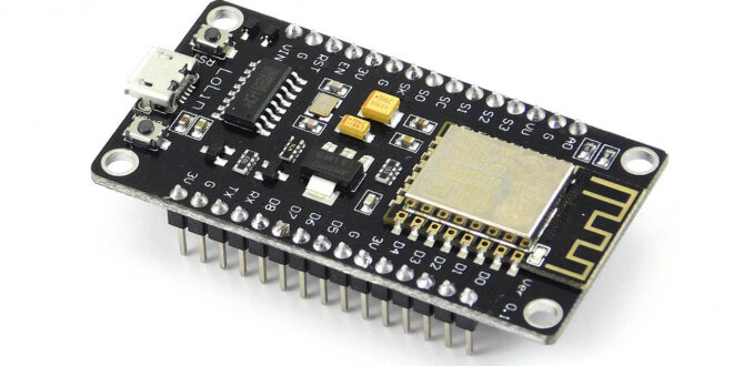
- Two ESP8266 modules (e.g., ESP-01 or NodeMCU)
- A DHT11 or DHT22 sensor (for temperature and humidity)
- Jumper wires
- Breadboard
Wiring Diagram
- Sender ESP8266 (with DHT sensor)
- Connect the DHT sensor as follows:
- VCC → 3.3V on ESP8266
- GND → GND
- DATA → GPIO 2 (D4 on NodeMCU)
- Connect the DHT sensor as follows:
- Receiver ESP8266: No additional connections needed, as it only serves to host the webserver.
Setting Up UDP Communication Between Two ESP8266 Modules
We'll first write code for the sender ESP8266, which reads data from the sensor and sends it via UDP. Then, we'll create a receiver ESP8266 that listens for incoming UDP packets and displays the data on a web page.
Code for Sender ESP8266
The sender reads data from a DHT sensor and sends it as a UDP packet to the receiver ESP8266.
Install the DHT Sensor Library
In the Arduino IDE, go to Sketch > Include Library > Manage Libraries and install the DHT sensor library by Adafruit.
#include <ESP8266WiFi.h>
#include <WiFiUdp.h>
#include "DHT.h"

#define DHTPIN 2 // Pin where the DHT sensor is connected
#define DHTTYPE DHT11 // DHT 11 or DHT22, change accordingly

// Your network credentials
const char* ssid = "your_SSID";
const char* password = "your_PASSWORD";

// Receiver ESP8266 IP address and port
const char* receiverIP = "192.168.1.100"; // Replace with the actual IP of the receiver
const unsigned int receiverPort = 4210; // The UDP port number

DHT dht(DHTPIN, DHTTYPE);
WiFiUDP udp;

void setup() {
   Serial.begin(115200);
   dht.begin();

// Connect to Wi-Fi
   WiFi.begin(ssid, password);
   while (WiFi.status() != WL_CONNECTED) {
      delay(1000);
      Serial.println("Connecting to WiFi...");
   }
   Serial.println("Connected to WiFi");
}

void loop() {
// Read temperature and humidity
   float h = dht.readHumidity();
   float t = dht.readTemperature();

   if (isnan(h) || isnan(t)) {
      Serial.println("Failed to read from DHT sensor!");
      return;
   }

// Prepare the UDP message
   String message = "Temperature: " + String(t) + " C, Humidity: " + String(h) + " %";
   Serial.println("Sending message: " + message);

// Send the message to the receiver ESP8266
   udp.beginPacket(receiverIP, receiverPort);
   udp.print(message);
   udp.endPacket();

   delay(2000); // Wait 2 seconds before sending the next packet
}
- WiFi Setup: The ESP8266 connects to the local Wi-Fi network using your SSID and password.
- DHT Sensor: Reads temperature and humidity from the DHT sensor.
- UDP Communication: The data is formatted as a string and sent via UDP to the receiver ESP8266 using WiFiUDP.
Code for Receiver ESP8266 (Web Server)
The receiver listens for UDP packets and displays the sensor data on a web page.
#include <ESP8266WiFi.h>
#include <WiFiUdp.h>
#include <ESP8266WebServer.h>

// Your network credentials
const char* ssid = "your_SSID";
const char* password = "your_PASSWORD";

// UDP settings
WiFiUDP udp;
unsigned int localPort = 4210; // The port to listen on
char incomingPacket[255]; // Buffer to hold incoming packets

// Web server object
ESP8266WebServer server(80);

String sensorData = "No data received";

void setup() {
   Serial.begin(115200);

// Connect to Wi-Fi
   WiFi.begin(ssid, password);
   while (WiFi.status() != WL_CONNECTED) {
      delay(1000);
      Serial.println("Connecting to WiFi...");
   }
   Serial.println("Connected to WiFi");
   Serial.print("IP Address: ");
   Serial.println(WiFi.localIP());

// Start UDP
   udp.begin(localPort);
   Serial.printf("Listening on UDP port %d\n", localPort);

// Start the web server
   server.on("/", handleRoot);
   server.begin();
   Serial.println("Web server started");
}

void loop() {
// Listen for incoming UDP packets
   int packetSize = udp.parsePacket();
   if (packetSize) {
      int len = udp.read(incomingPacket, 255);
      if (len > 0) {
         incomingPacket[len] = 0;
      }
      Serial.printf("UDP packet received: %s\n", incomingPacket);
      sensorData = String(incomingPacket);
   }

// Handle web server requests
   server.handleClient();
}

// Function to handle the web page
void handleRoot() {
   String html = "<html><body><h1>Sensor Data</h1>";
   html += "<p>" + sensorData + "</p>";
   html += "</body></html>";
   server.send(200, "text/html", html);
}
Code Breakdown (Receiver):
- UDP Listener: The ESP8266 listens for incoming UDP packets on a specified port. When a packet is received, the sensor data is extracted and stored.
- Web Server: Hosts a simple web server that serves a page displaying the latest sensor data. The data is refreshed every time the user accesses the page.
Setting Up the IP Address of the Receiver
To ensure communication between the two ESP8266 modules, you need to know the IP address of the receiver ESP8266. After uploading the code, open the Serial Monitor to find the IP address of the receiver. Then, update the receiverIP in the sender code with this address.
Viewing the Sensor Data
- Power up both ESP8266 modules. The sender will read data from the DHT sensor and send it to the receiver via UDP.
- Open a web browser on a device connected to the same Wi-Fi network and enter the IP address of the receiver ESP8266 (as shown in the Serial Monitor).
- The web page will display the current sensor readings (temperature and humidity), which are updated every 2 seconds.
Conclusion
By using UDP communication between two ESP8266 modules, you can efficiently send real-time sensor data from one ESP to another and visualize the data via a web server. This project demonstrates how easy it is to set up wireless communication for IoT applications, offering a foundation to build more complex systems such as remote monitoring, smart home devices, or industrial sensors.


