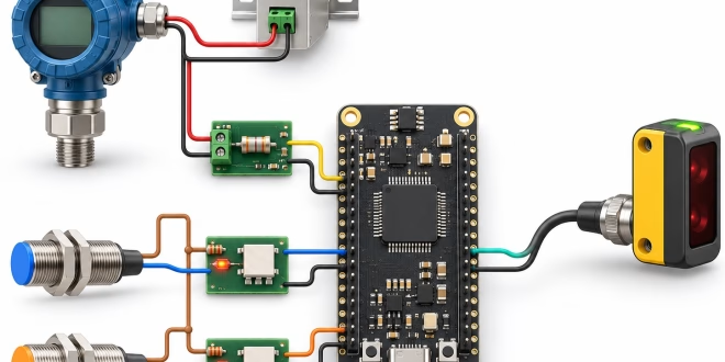
Tutorial projects usually meet sensors in their friendliest form: a DHT22 on a breakout board, 3.3 V in, clean digital out. Industrial sensors play by different rules — 24 V supplies, current-loop signalling, and outputs designed to survive electrically noisy cabinets. The good news is that the interface circuits are simple once you know what the sensor is actually doing. This guide covers the three cases you will meet first.
Case 1: The 4–20 mA current loop
The 4–20 mA loop is the workhorse of process instrumentation (pressure, temperature, level, flow) because current does not drop over long cable runs and a broken wire is detectable: 4 mA means "zero reading", 0 mA means "fault".
To read it with a microcontroller ADC, pass the loop current through a precision shunt resistor and measure the voltage:
| Loop current | Voltage across 250 Ω shunt | Meaning |
|---|---|---|
| 4 mA | 1.0 V | Zero / minimum reading |
| 12 mA | 3.0 V | Mid-scale |
| 20 mA | 5.0 V | Full scale |
| 0 mA | 0 V | Wire break or sensor fault |
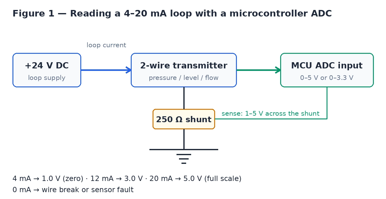
A 250 Ω, 0.1% resistor converts the loop to a 1–5 V signal. Two practical notes:
- If your ADC is 3.3 V only, use a 165 Ω shunt instead (0.66–3.3 V) and scale in software.
- Most loop transmitters are powered from the loop (2-wire devices). Your interface must supply the 24 V loop power and respect the transmitter's minimum voltage after the shunt drop.
Case 2: PNP and NPN discrete outputs
Proximity, photoelectric and level sensors in 3-wire DC form switch either the positive rail (PNP, "sourcing") or ground (NPN, "sinking"):
- PNP output gives you ~24 V when active. Feed a microcontroller pin through a voltage divider (e.g. 10 kΩ / 2.2 kΩ) or, better in a noisy cabinet, an optocoupler.
- NPN output pulls the line to ground when active. Use a pull-up to your logic rail (with an optocoupler if you want isolation) and read it as active-low.
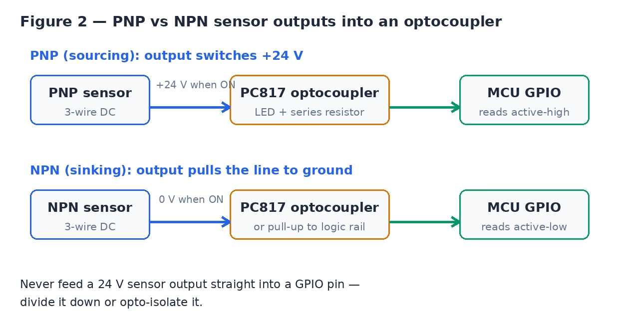
The mistake to avoid: connecting a 24 V sensor output "temporarily" to a 5 V-tolerant pin to see if it works. It works exactly once. A PC817 optocoupler, a series resistor sized for the sensor's output current, and a transistor output stage cost cents and make the interface boring — which is what you want.
Case 3: IO-Link, the digital upgrade
IO-Link (IEC 61131-9) runs over the same 3 wires as a standard sensor but adds a digital channel: the sensor reports its measured value plus diagnostics (device ID, temperature warnings, signal quality). From the microcontroller side you do not bit-bang it — you use an IO-Link master IC or a ready master module and talk to it over SPI or UART. Choose it when you are designing something new; for retrofits, the analogue and discrete interfaces above are what the installed base speaks.
A note on replacement parts
Prototypes and repairs run into one recurring problem: the sensor on the machine is discontinued, and its modern successor has a different output or connector. Before redesigning the interface, check whether the original model is still obtainable — industrial parts catalogues such as INDPRT list current and discontinued sensors by exact model number, which is how the installed base is actually identified. Match the designation character for character; on industrial labels the suffix usually encodes the output type (PNP versus NPN) or the connection style, and "almost the same model" is a different sensor.
Summary
- 4–20 mA → shunt resistor, measure voltage, treat 0 mA as a fault, not a reading.
- PNP/NPN → divide or opto-isolate down to logic level; never feed 24 V to a GPIO.
- IO-Link → use a master IC; it is a protocol, not a voltage.
- Replacements → identify by exact designation first, redesign second.