
Most people have nightmares about PIC assembly language programming while some would say it's a waste of time. I've experienced both so I agree. PICs can be programmed much easier using high-level languages like C and Basic. However, learning to code in assembly helps you learn more about the microcontroller's internal hardware. This in turn allows you to tailor-fit programs according to your intention. In embedded systems, where performance is critical and code is hardware specific, this is very important. This tutorial will help you start learning PIC assembly language programming.
Why Learn Assembly
High-level languages often have additional headers that take up program memory space. In microcontroller programming, saving program space is essential as you only have a few to work on. Take this simple LED blink program written in XC8, for example:
#define _XTAL_FREQ 4000000 //4 MHz crystal
#include <xc.h>

void main(void)
{
  TRISB0 = 0; //make RB0 output
  while(1)
  { //infinite loop
     RB0 = 1; //set pin
     __delay_ms(65); //65 millisecond delay between
     RB0 = 0; //clear pin
     __delay_ms(65);
   } return;
}
This code when compiled and assembled generates a 182-byte hex file. Now take this PIC assembly code which does the same thing as the code above:
;TODO INSERT CONFIG CODE HERE USING CONFIG BITS GENERATOR
#INCLUDE <P16F84A.INC>
RES_VECT CODE 0x0000 ; processor reset vector
GOTO START ; go to beginning of program

; TODO ADD INTERRUPTS HERE IF USED

CBLOCK 0x0C
COUNT1
COUNT2
ENDC

MAIN_PROG CODE ; let linker place main program

START
BSF STATUS, RP0
MOVLW 0xFE
MOVWF TRISB
BCF STATUS, RP0

MAIN
BSF PORTB,0
CALL DELAY
BCF PORTB,0
CALL DELAY
GOTO MAIN

DELAY
LOOP1 DECFSZ COUNT1, 1
GOTO LOOP1
DECFSZ COUNT2,1
GOTO LOOP1
RETURN

END
The hex file for this code is 163 bytes. A 19 byte difference in microcontroller programming is already significant!
Our First PIC Assembly Language Code
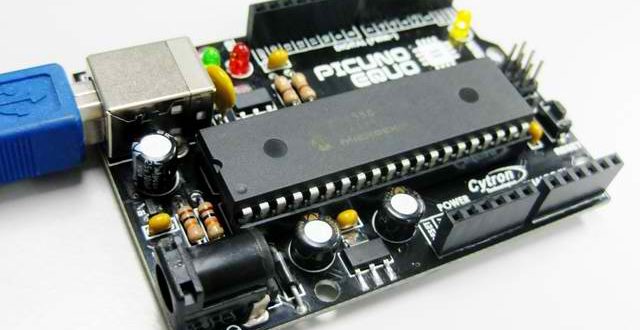
As an introduction to PIC assembly programming, we'll be using PIC16F84A, a x14 architecture microcontroller by Microchip. This is the chip we introduced in the previous article. The PIC1684A, having only a few registers to work with, is good for beginners to microcontroller programming.
We'll take a look again at the assembly code posted above:
; TODO INSERT CONFIG CODE HERE USING CONFIG BITS GENERATOR
#INCLUDE <P16F84A.INC>
RES_VECT CODE 0x0000 ; processor reset vector
GOTO START ; go to beginning of program

; TODO ADD INTERRUPTS HERE IF USED

CBLOCK 0x0C
COUNT1
COUNT2
ENDC

MAIN_PROG CODE ; let linker place main program

START
BSF STATUS, RP0
MOVLW 0xFE
MOVWF TRISB
BCF STATUS, RP0

MAIN
BSF PORTB,0
CALL DELAY
BCF PORTB,0
CALL DELAY
GOTO MAIN

DELAY
LOOP1 DECFSZ COUNT1, 1
GOTO LOOP1
DECFSZ COUNT2,1
GOTO LOOP1
RETURN

END
One thing you need to understand is that assembly code is processed line by line. The speed at which is line is processed is the microcontroller's instruction cycle. The instruction cycle time is given as:
Where fosc is the oscillator clock frequency. This tells us that the instruction cycle is dependent on the value of the crystal oscillator you are using. A common crystal oscillator value is 4 MHz so:
We'll go back to this later.
Save up to 50% on select Microchip Development Kits
Dissecting the Code
In assembly programming, it is important to provide comments on the code so that it is easier to trace. Comments in assembly starts with a semicolon like this:
;this is a comment
There are a number of comments on the assembly program above.
The first significant line on the program is
#INCLUDE <P16F84A.INC>
This tells the assembler to add the include file for this particular microcontroller. Each microcontroller has their own include file which can be found in C:\Program Files (x86)\Microchip\MPASM Suite folder. The include file makes it possible to call on the register's name rather than its address.
Microcontroller programming in assembly focuses on manipulating the registers. Here are the registers of the PIC16F84A:
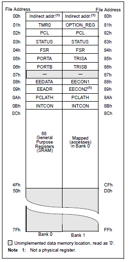
As we go along with this tutorial, we get to know the function of each register shown.
The next signficant lines on the program is
RES_VECT CODE 0x0000        ;processor reset vector
GOTO START                  ;go to beginning of program
These gives the reset vector for the code. A reset vector points to which part of the program is the first one to be executed. Here, that part is the one with the label START. Another vector used is the INT_VECT or interrupt vector. This vector is discussed in the interrupt tutorial.
Open the P16F84A.INC file and check out its contents. Make sure not to change anything inside it, unless you know what you're doing.
CBLOCK
The lines,
CBLOCK 0x0C
 COUNT1
 COUNT2
ENDC
use the CBLOCK assembly operative. This assigns the aliases COUNT1 and COUNT2 to the general purpose registers with address 0Ch and 0Dh respectively. If you look at the PIC16F84A's register file map above, these address are part of SRAM and don't have specific names. It means we can use them any way we like. The COUNT1 and COUNT2 registers will be used for our delay subroutine.
Changing Banks
The actual program execution starts on the line,
BSF STATUS, RP0
The command BSF stands for "bit set register f" where the next statement is the register f and the bit associated with that register. View the rest of the instruction set. For the one above, the register f is the STATUS register:
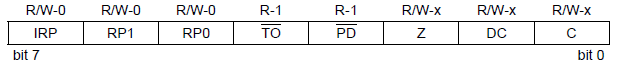
The RP0 bit is called the Register Bank Select Bit. The PIC16F84A groups its registers into two banks. Let's look at the device's register map again:
Before you are able to manipulate a specific register, you must first go to the bank where it is located. This is done via clearing (make it zero) or setting (make it one) the RP0 bit. Note that some registers including the STATUS register are located in both banks which means you don't need to switch banks to access them.
TRIS Register
So why did we set the RP0 bit? That is because the next lines,
MOVLW 0xFE
MOVWF TRISB
uses the register TRISB which is located at bank 1.
The operative MOVLW means "move literal value to W register". The W register is a general purpose register which acts as a temporary storage as you move values from register to register.
The operative MOVWF means "move the contents of W to TRISB". This means that after these two lines, the TRISB register now has the value 0xFE.
So why this value to TRISB? First we'll discuss the function of the TRISB register.
TRIS is short for tri-state. This describes the characteristics of the ports of the microcontroller meaning the a port can be an (1) input, (2) output or (3) left hanging. The PIC16F84A has two ports: PORTA and PORTB. This means there are also two TRIS registers: TRISA and TRISB. A zero in any TRIS bit makes the corresponding PORT bit an output. Conversely, a one in any TRIS bit makes the corresponding PORT bit an input.
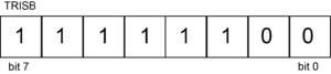
For our example, the value of TRISB is 0xFE:
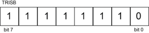
You see that only bit 0 is low or cleared. This corresponds to PORTB.0 or RB0 becoming an output pin and the rest as input pins. If for example you want to make PORTB.0 and PORTB.1 output pins and the rest as input pins, then your TRISB would be:
which is 0xFC in hexadecimal value.
The next line:
BCF STATUS, RP0
simply brings us back to bank 0 because the next lines:
MAIN
   BSF PORTB, 0
   CALL delay
   BCF PORTB, 0
   CALL delay
   GOTO main
involves the use of the PORTB register which is located in bank 0.
The op code BSF stands for "bit set f". The line BSF PORTB, 0 command sets bit zero of the PORTB register. Remember that the PORTB register is the one tied to the physical RB pins. So when PORTB.0 is set, the RB0 pin is high.
The line BCF PORTB, 0 does the opposite of the command just discussed. This will make the RB0 pin low.
Delay Subroutine
In between the bsf and bcf commands is a call to the delay subroutine which is found at the end part of the code:
DELAY
 LOOP1 DECFSZ COUNT1, 1
 GOTO LOOP1
 DECFSZ COUNT2,1
 GOTO LOOP1
 RETURN
Why is this routine needed? As mentioned above, each line is processed at a speed of 1 microseconds for a 4 MHz crystal oscillator. If there is no delay subroutine, the time between RB0 being high and then low would just be 1 microsecond! The LED blinking will be too fast to see in real time.
The DECFSZ operative, used in the delay subroutine, is short for "decrement f skip if zero". It would decrement COUNT1 until it reaches zero and then it will skip the next line. If the COUNT1 is still not zero, the program will process the loop as indicated by the "goto loop1" instruction. The number "1" next to COUNT1 means the result of the decrement is placed to COUNT1. The other possible value here is "0" which will place the result of the decrement to the W register.
By the way, COUNT1 has an initial value of 0xFF or 255. This is the default value of unused registers. This means the loop will continue for 255 instruction cycles!
Once COUNT1 reaches zero, it will exit the loop and go to the DECFSZ COUNT2, 1 line. This will decrement COUNT2 but the you'll see that the next line points the program back to loop1! This means COUNT1 will be decremented again and again until it reaches zero. After that, COUNT2 (now with a value of 254) will be decremented and the loop continues.
All in all, the routine would take 255 x 255 instruction cycles to process. This is equivalent to 65 ms of waiting time.
Summary
Our first PIC assembly language program can now be summarized from top to bottom:
- Point the label START as the first line in the program (lines 3 and 4)
- Register COUNT1 and COUNT2 as variables for the delay subroutine(8 to 11)
- Go to bank 1 and set RB0 as output and then go back to bank 0 (lines 16 to 19)
- Set RB0, wait for 65 ms (with the help of the delay subroutine in lines 22 to 23)
- and then clear it then wait for 65 ms again (lines 24 to 25)
- Go back to the portion of the program with label "main", effectively looping the code endlessly (line 26)
- Start of delay subroutine (line 28)
- End of program (line 35)
That's it! I suggest you try the above code and use the circuit provided on this article. Also, check out all the assembly instructions. Have fun coding in PIC assembly language!


