
Simply put, synchronous serial protocols like SPI and I2C have a separate line for timing (the CLK line) while asynchronous protocols like UART (RS232) don’t. The addition of a clock line makes reception timing much easier and thus reduces transmission errors.
It is also possible to interconnect more than two devices with synchronous protocols because there is no need for two devices to have the same data rates: one device (master) sets the data rate for everyone (slaves).
Why Use SPI
Synchronous protocols are also faster because of the type of drivers used. While asynchronous serial is sufficient for most projects, there are instances that you will need more speed like accessing memory cards or liquid crystal displays. The UART baud rate of the PIC16F877A in high-speed mode is calculated according to the formula:
![]()
Where X is the contents of the SPBRG register which is up to 255 only. So let’s say that we set SPBRG = 0 and use the recommended maximum frequency of 20 MHz, then the highest baud rate possible for the said microcontroller would be
![]()
In UART, the baud rate is the same as the bit rate so we can also say that the maximum transfer rate is 1.25 Mbps. If a higher oscillator frequency is selected through overclocking (which is possible at the expense of stability), this rate would be higher.
Now let’s look at SPI, whose maximum bit rate is Fosc/4. Using the same 20 MHz oscillator, the maximum data rate would be 5 Mbps! That’s 4 times the speed of UART on the same device using the same oscillator.
Speed and multiple connections are the primary reasons for using SPI over UART. A separate SPI tutorial is provided for more information. For the rest of this article, I will cover how to implement the SPI protocol in PIC microcontrollers.
Read the SPI Protocol Guide to learn more about SPI
The MSSP Module
The synchronous protocols SPI and I2C are managed by the Master Synchronous Serial Port (MSSP) module. This module is not part of the PIC16F84A features so for the rest of this tutorial, we'll be using the PIC16F877A.
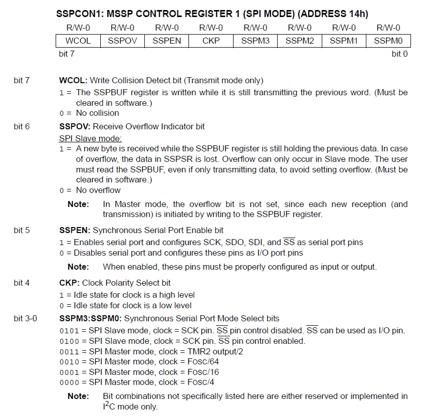
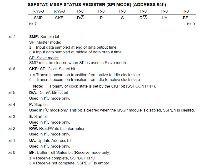
There are three registers associated with this module: SSPSTAT, SSPCON, and SSPCON2. The use of each register is different in SPI and I2C modes. SPI mode only uses the SSPSTAT and SSPCON registers. The I2C mode is covered in part two of this tutorial.
Here are the above-mentioned registers:
Configuring SPI
During initialization, we’ll need to configure the SMP (if the device is the master) and CKE bits of SSPSTAT. Then, the SSPEN bit must be set to enable the pins RC3 (SCK), RC4 (SDI), and RC5 (SD0). We may also need to configure the CKP bit of SSPCON1.
The SMP, CKE, and CKP bit settings must be the same for the master and the slave. Here, we will take a sample in the middle of data output time, use idle to active transmission, and make a low level an idle state. This means the three bits will be cleared.
The SPI data rate is configured using the last four bits of SSPCON1:
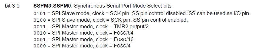
Basically, any data to be sent via SPI must be placed inside the SSPBUF register. Conversely, any data received is inside the SSPBUF register. The BF bit of SSPSTAT will be set if data is available.
SPI in PIC ASM
Below are two ASM codes, one for a master and another for a slave device, where the master sends data to the slave:
Master Code:
INCLUDE <P16F877A.INC>

   RES_VECT  CODE    0x0000            ; processor reset vector
   GOTO    START                       ; go to beginning of program

MAIN_PROG CODE                      ; let linker place main program

cblock 0x20
   val
   count1
   count2
endc

START
   clrf val
   bcf STATUS, RP0      ;bank 0
   movlw 0x20           ;enable sync serial port, master mode at Fosc/4
   movwf SSPCON
   bsf STATUS, RP0      ;bank 1
   clrf SSPSTAT         ;data sampled at the middle, idle to active clock state
   bcf TRISC,3          ;CLK is output
   bcf TRISC,5          ;SDO is output
   bcf STATUS, RP0      ;bank 0

MAIN
   movf val,W           ;move contents of val to W
   movwf SSPBUF         ;then move to SSPBUF
   call DELAY           ;some delay
   incfsz val,1         ;increment val
   goto MAIN            ;until overflow
   comf val,1           ;when overflowed, complement to go back to 255 then to zero
   goto MAIN            ;repeat

DELAY                   ;delay subroutine
loop1 decfsz count1,1
       goto loop1
decfsz count2,1
       goto loop1
return

END
Slave Code:
INCLUDE <P16F877A.INC>

   RES_VECT  CODE    0x0000      ; processor reset vector
   GOTO    START                           ; go to beginning of program

MAIN_PROG CODE                      ; let linker place main program

START
   movlw 0x24           ;configured as slave with SS enabled
   movwf SSPCON
   bsf STATUS,RP0       ;bank 1
   bcf TRISC,5          ;SDO pin as output
   bsf TRISC,3          ;SCK pin as input
   bsf TRISA,5          ;SS pin as input
   clrf TRISB           ;all PORTB as output
   movlw 0x07
   movwf ADCON1         ;needed to turn off ADC so we can use RA5 as digital pin
   clrf SSPSTAT         ;data sampled at the middle, idle to active clock state

MAIN
   btfss SSPSTAT, BF    ;check if buffer is full
   goto MAIN            ;if not check again
   bcf STATUS, RP0      ;if there is data, move to bank 0 and
   movf SSPBUF, W       ;move contents of buffer to PORTB
   movwf PORTB
   bsf STATUS, RP0      ;bank 1
   goto MAIN

END
SPI uses a Master-Out-Slave-In (MOSI) line and a Master-In-Slave-Out (MISO) line. In PICs, they are named SDI and SDO respectively. Of course, you also have the clock line or SCK/SCL. The slave select (SS) pin is used for multiple slave connections. When a slave's SS pin is pulled low, this means the master is "talking" to him. In our example which uses only one slave device, we connected the SS pin to the ground.
This is the schematic for the codes above (note that oscillator and pull-up resistors have been omitted):
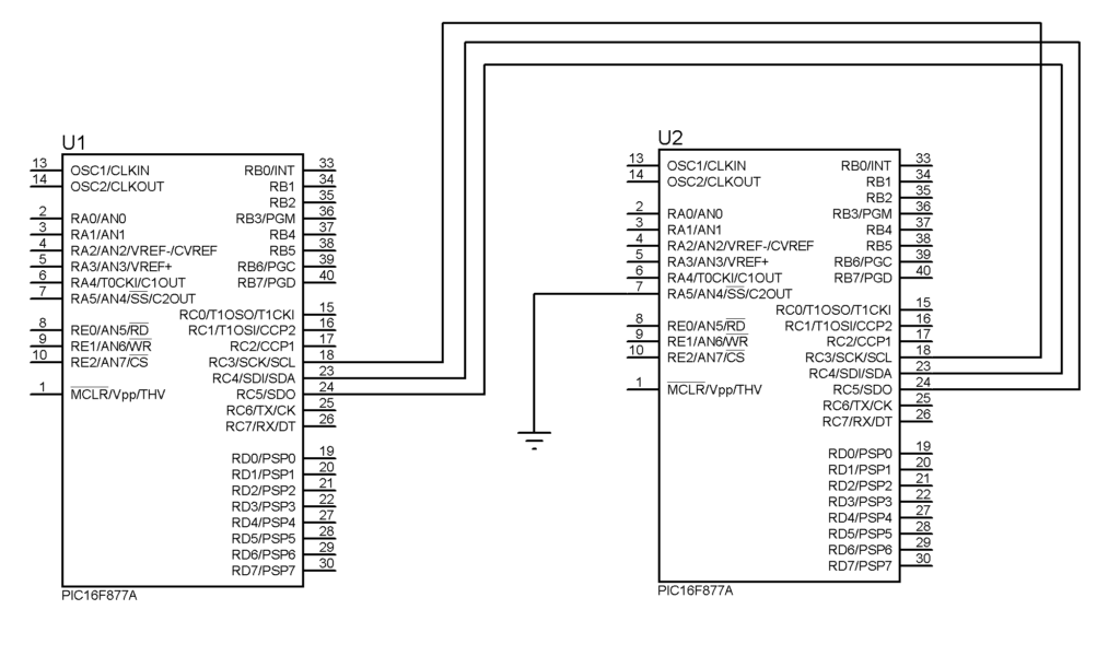
The master device increments a variable and sends the value of each increment via the SPI bus. The slave device receives the value and displays it as PORTB values.
SPI in XC8
Here’s how the above code can be implemented in XC8:
Master Code:
#define _XTAL_FREQ 4000000
#include <xc.h>

void main(void) {
   SSPCON = 0x20;
   SSPSTAT = 0;
   TRISC3 = 0;
   TRISC5 = 0;

   int i = 0;
   while(1){
      SSPBUF = i;
      i++;
      __delay_ms(100);
   }
}
Slave Code:
#define _XTAL_FREQ 4000000
#include <xc.h>

void main(void) {
   SSPCON = 0x24;
   SSPSTAT = 0;
   TRISB = 0;
   TRISC5 = 0;
   TRISC3 = 1;
   ADCON1 = 7;
   TRISA5 = 1;

   while(1){
       if(BF){
           PORTB = SSPBUF;
           __delay_ms(100);
       }
   }
}
Custom SPI Library
We can simplify the use of SPI in XC8 using a custom library. I created "spi.h" with three functions, spiBegin(), spiWrite(), and spiRead(). The spiBegin() accepts three parameters: mode, sample bit, clock edge select, and clock polarity. Here are all the possible values for each parameter:
mode:
- MASTER_OSC_DIV4
- MASTER_OSC_DIV16
- MASTER_OSC_DIV64
- MASTER_TMR2_DIV2
- SLAVE_SS_EN
- SLAVE_SS_DIS
sample bit:
- SAMPLE_MIDDLE
- SAMPLE_END
clock edge select:
- IDLE_TO_ACTIVE
- ACTIVE_TO_IDLE
clock polarity:
- IDLE_HIGH
- IDLE_LOW
The spiWrite() and spiRead() functions are used to write and read from SSPBUF, respectively.
Here is "spi.h" which should be added to your project's Header Files folder:
// This is a guard condition so that contents of this file are not included
// more than once.
#ifndef XC_HEADER_TEMPLATE_H
#define	XC_HEADER_TEMPLATE_H

#include <xc.h> // include processor files - each processor file is guarded.

typedef enum
{
  MASTER_OSC_DIV4  = 0b00100000,
  MASTER_OSC_DIV16 = 0b00100001,
  MASTER_OSC_DIV64 = 0b00100010,
  MASTER_TMR2_DIV2 = 0b00100011,
  SLAVE_SS_EN      = 0b00100100,
  SLAVE_SS_DIS     = 0b00100101
}Spi_Mode;

typedef enum
{
  SAMPLE_MIDDLE = 0b00000000,
  SAMPLE_END    = 0b10000000
}Spi_Data_Sample;

typedef enum
{
  IDLE_HIGH = 0b00001000,
  IDLE_LOW  = 0b00000000
}Spi_Clock_Pol;

typedef enum
{
  IDLE_TO_ACTIVE = 0b00000000,
  ACTIVE_TO_IDLE = 0b01000000
}Spi_Clock_Edge;

void spiBegin(Spi_Mode sMode, Spi_Data_Sample sDataSample, Spi_Clock_Edge sClockEdge, Spi_Clock_Pol sClockPol)
{
  TRISC5 = 0;
  if(sMode & 0b00000100) //If Slave Mode
  {
    SSPSTAT = sClockEdge;
    TRISC3 = 1;
  }
  else //If Master Mode
  {
    SSPSTAT = sDataSample | sClockEdge;
    TRISC3 = 0;
  }
  SSPCON = sMode | sClockPol;
}

void spiWrite(char dat){
    SSPBUF = dat;
}

char spiRead(){
    if(BF){
        return SSPBUF;
    }
}

#endif	/* XC_HEADER_TEMPLATE_H */
Here are example codes that use the library:
Master with SPI Library
#define _XTAL_FREQ 4000000
#include <xc.h>
#include "spi.h"

void main(void) {
    spiBegin(MASTER_OSC_DIV4, SAMPLE_MIDDLE, IDLE_TO_ACTIVE, IDLE_LOW);
    int i = 0;

    while(1){
        spiWrite(i);
        i++;
    }
}
Slave with SPI Library
#define _XTAL_FREQ 4000000
#include <xc.h>
#include "spi.h"

void main(void) {
    spiBegin(SLAVE_SS_DIS, SAMPLE_MIDDLE, IDLE_TO_ACTIVE, IDLE_LOW);
    TRISB = 0;

    while(1){
        PORTB = spiRead();
    }
}
Once you get a grip on how SPI works, you can now use it to communicate with SD cards or liquid crystal displays.
On the next page, we will look at how to use the I2C mode of the MSSP module.


 Communication with PIC16F877A")

