When developing embedded systems, a USB-to-UART converter is probably one of the first tools you will add to your workbench. However, UART at 3.3 V or 5 V logic levels is not the only type of serial communication you will encounter. Industrial controllers, older equipment, PLCs, sensors, motor drives, and other devices commonly use RS232 or RS485 instead.
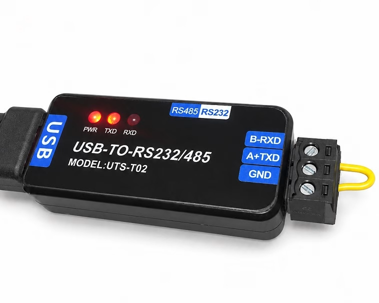
I recently picked up a small tool that combines both interfaces in one device: the UTS-T02 USB-to-RS232/RS485 converter. A slide switch selects between RS232 and RS485 operation, while three LEDs indicate power, transmit activity, and receive activity. The unit also uses a removable three-position screw terminal instead of permanently attached wires. The product listing identifies the USB interface chip as the CH343G.
This is a simple device, but it can be surprisingly useful when developing or troubleshooting embedded systems. In this article, we'll look at what it does, how the two modes differ, and how we can actually use it to communicate with embedded hardware.
What Does the USB to RS232/RS485 Converter Do?
The job of the converter is simple: it gives a computer an RS232 or RS485 serial interface through USB.
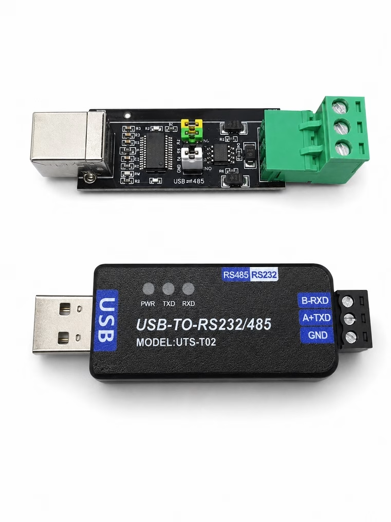
Once connected, the computer sees the converter as a serial port. A serial terminal, Python program, test application, Modbus utility, or other PC software can then use that serial port to communicate with the external device.
The CH343 used inside this converter is a USB-to-UART bridge from WCH. The CH343 family supports virtual serial-port operation and baud rates from 50 bps up to 6 Mbps at the chip level. The maximum speed of the complete UTS-T02 should not automatically be assumed to be 6 Mbps, however, because the RS232/RS485 transceiver circuitry also affects the usable communication rate.
The interesting part of this particular adapter is that the UART signal generated internally is converted into one of two different electrical interfaces:
- RS232 for point-to-point serial communication
- RS485 for differential serial communication, particularly over longer cables and in electrically noisy environments
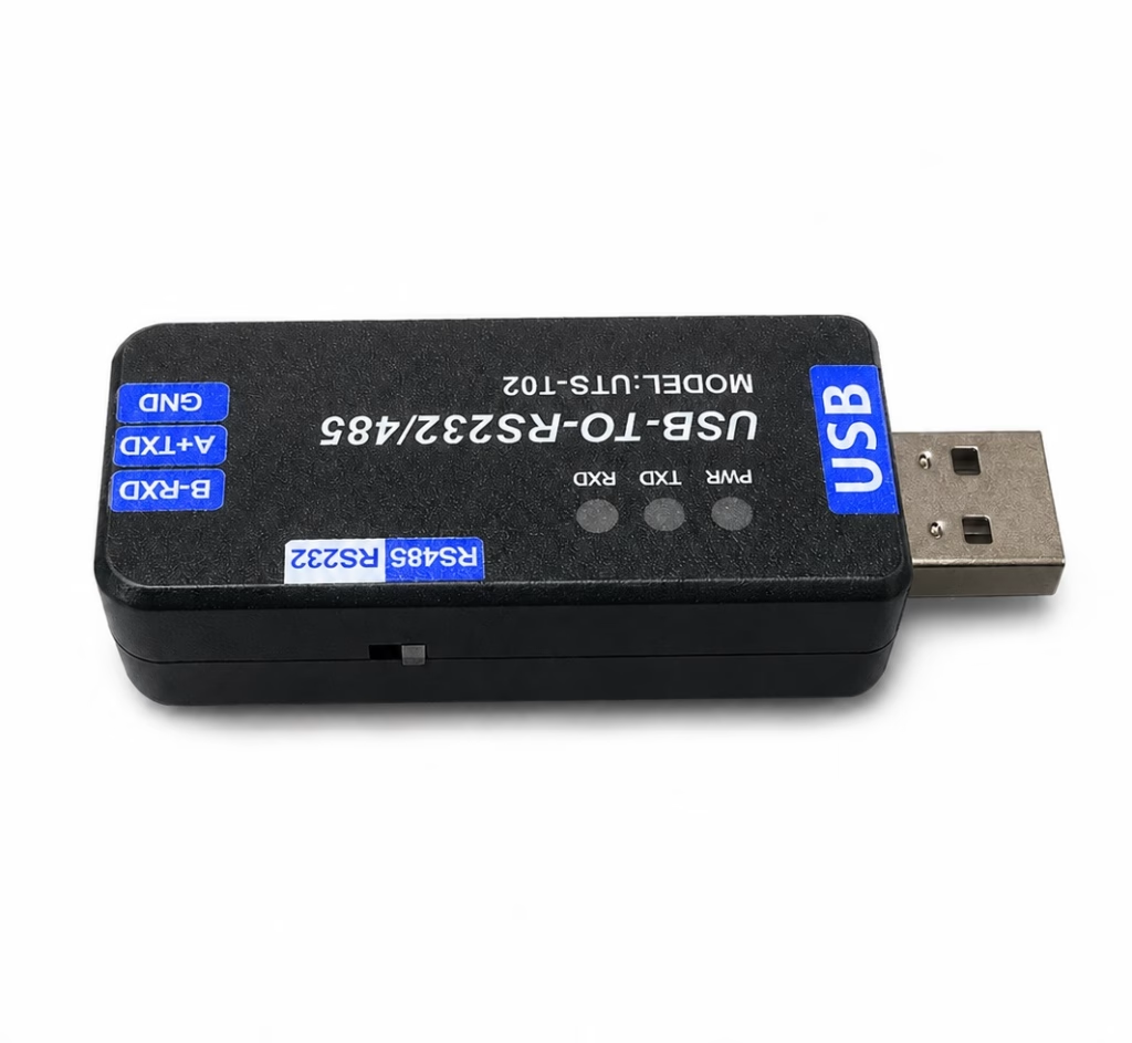
A small switch on the side selects which interface is connected to the terminal block.
Understanding the Terminals
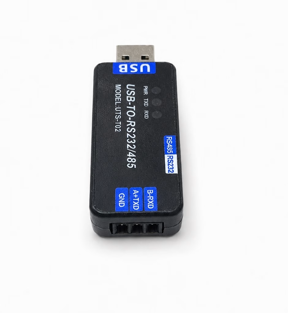
There are only three terminals on the end of the converter:
| Terminal | RS485 Mode | RS232 Mode |
|---|---|---|
| GND | Ground/reference | Ground |
| A+ / TXD | A differential line | Transmit |
| B- / RXD | B differential line | Receive |
The dual labels initially look strange because the same physical terminals serve completely different purposes depending on the switch position. The seller's interface diagram describes the A+/TXD terminal as RS485 A or the connection toward the RS232 receiver, while B-/RXD becomes RS485 B or the connection toward the RS232 transmitter.
For normal RS232 wiring, remember that the transmitter of one device connects to the receiver of the other:
USB Converter             RS232 Device

TXD  -------------------> RXD
RXD  <------------------- TXD
GND  -------------------- GND
In RS485 mode, the wiring instead becomes:
USB Converter             RS485 Device

A+   -------------------- A
B-   -------------------- B
GND  -------------------- GND
RS232 Is Not TTL UART
This is one of the most important things to understand about this tool.
Do not connect the RS232 terminals directly to an ESP32, Arduino, Raspberry Pi Pico, STM32, or similar microcontroller UART.
The UART peripheral inside a microcontroller normally operates at logic levels such as 3.3 V. RS232 uses positive and negative voltages instead. Valid RS232 receiver signals are normally greater than +3 V or less than -3 V, with transmitter levels typically extending farther in either direction.
If your microcontroller has a normal TTL/CMOS UART, you need an RS232 transceiver such as a MAX3232 between the microcontroller and this adapter.
Computer
   |
  USB
   |
UTS-T02
(RS232)
   |
 RS232
   |
MAX3232
   |
3.3 V UART
   |
 ESP32
This also means that the UTS-T02 does not replace the common CH340, CP2102, or FT232 USB-to-TTL adapters used when programming or debugging development boards. It serves a different purpose.
What’s Inside the UTS-T02?
Since this adapter combines USB, RS232, and RS485 in such a small enclosure, I decided to open it and see what hardware is actually doing the conversion.
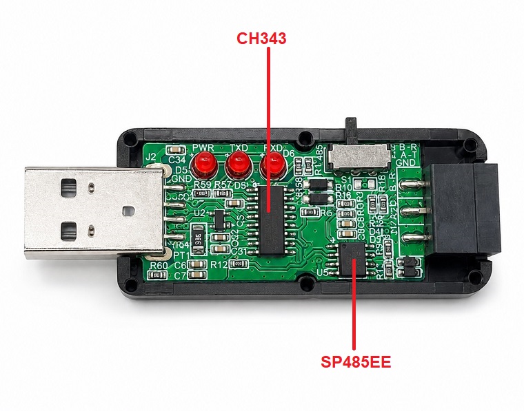
There are two main ICs on the PCB. The larger chip is a WCH CH343, which handles the USB-to-UART conversion. The smaller chip is an SP485EE, a half-duplex RS485 transceiver responsible for converting the UART signals into the differential A and B signals used by RS485.
The basic RS485 signal path is therefore:
PC USB
   |
   v
CH343
USB-to-UART
   |
   v
SP485EE
RS485 Transceiver
   |
   +---- A+
   |
   +---- B-
The RS485 side is straightforward, but the RS232 side was more interesting. There is no obvious MAX232 or MAX3232-style RS232 transceiver on the board. At first glance, this raises the possibility that the terminal marked RS232 might simply expose logic-level UART signals from the CH343.
Is the RS232 Output Really RS232?
To find out, I switched the adapter to RS232 mode and measured the TXD terminal relative to GND.
With the serial port idle, I measured approximately -5 V at TXD. I then repeatedly transmitted the character U from the PC and observed the TXD signal using an oscilloscope. The waveform switched between positive and negative voltages rather than between 0 V and a positive logic voltage.
This is important because a normal TTL or CMOS UART would typically switch between 0 V and 3.3 V or 5 V. RS232 instead uses bipolar signaling, where the idle or mark state is represented by a negative voltage.
TTL UART:

Logic high  ---- +3.3 V or +5 V
Logic low   ---- 0 V


UTS-T02 RS232 TX:

Idle        ---- approximately -5 V
Data        ---- switches between
                positive and negative voltages
The character U is particularly useful for viewing a serial waveform because its hexadecimal value is 0x55, or 01010101 in binary. This creates frequent transitions in the transmitted data and makes the signal easy to observe on an oscilloscope.
Based on these measurements, the UTS-T02's RS232 setting is not simply exposing the CH343's logic-level UART. The board contains additional circuitry that converts the UART signal into bipolar RS232 voltage levels, even though this circuitry is not implemented using an obvious dedicated MAX232-family IC.
The internal architecture therefore appears to be approximately:
                         +---- RS232 level conversion ---- TXD/RXD
                         |
USB ---- CH343 ---- UART-+
                         |
                         +---- SP485EE ------------------- A+/B-
                                  RS485
I haven't reverse-engineered every component of the RS232 level-conversion circuit, so I won't claim exactly how the positive and negative voltages are generated. However, the measured -5 V idle level and bipolar transmit waveform confirm that the output behaves electrically as an RS232 interface rather than an ordinary TTL UART.
Testing RS232 Mode
The easiest first test for the RS232 side is a loopback test.
Set the switch to RS232 and connect the TXD and RXD terminals together. Connect the converter to the computer and determine which COM port has been assigned to it.
Open your preferred serial terminal and configure a reasonable baud rate such as:
- 9600 baud
- 8 data bits
- No parity
- 1 stop bit
- No flow control
Characters transmitted by the PC should return through the RXD terminal and appear in the terminal program.
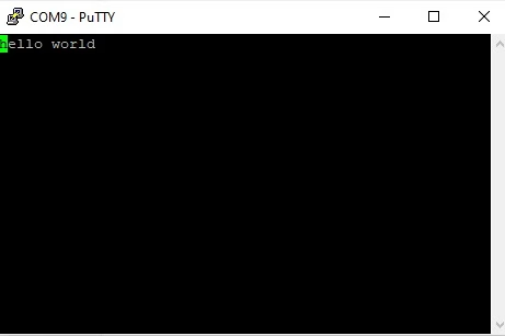
This is a useful first check because it verifies the USB interface, serial driver, transmit circuit, receive circuit, and terminal connection without requiring another device.
Using RS232 with a Microcontroller
To test this converter against a microcontroller, we can put a MAX3232 between the adapter and the MCU.
UTS-T02 TXD ---- MAX3232 ---- MCU RX
UTS-T02 RXD ---- MAX3232 ---- MCU TX
UTS-T02 GND ----------------- MCU GND
You can then run a simple UART echo program on the microcontroller. Anything typed into the PC terminal is sent through USB, converted to RS232, converted back to logic-level UART by the MAX3232, and finally received by the microcontroller.
The response travels through exactly the opposite path.
This setup can be useful when developing equipment that must eventually communicate with an existing RS232 system. Instead of requiring the actual equipment during every firmware test, the PC and converter can act as the other end of the serial connection.
RS485 Mode
RS485 is where this converter becomes particularly useful for embedded development.
Unlike the single-ended RS232 interface, RS485 uses differential signaling. Information is represented by the voltage difference between two wires rather than the voltage of a single signal relative to ground. This makes RS485 much better suited to long cables and electrically noisy environments. RS485 also supports multiple nodes on the same bus.
The UTS-T02 is designed for two-wire half-duplex RS485. Half-duplex means the same pair of wires is used for both transmitting and receiving, so only one device should drive the bus at a time. Two-wire half-duplex is the most common RS485 configuration.
                 RS485 BUS

UTS-T02     Device 1       Device 2
  A ----------- A ------------ A
  B ----------- B ------------ B
 GND ---------- GND ---------- GND
Unlike an RS485 transceiver attached directly to a microcontroller, the converter does not expose separate Driver Enable and Receiver Enable pins. From the user's perspective, direction switching is therefore handled inside the adapter when operating in RS485 mode.
Testing RS485 with an ESP32
For a practical test, we can connect the UTS-T02 to an ESP32 through a 3.3 V-compatible RS485 transceiver such as the MAX3485.
| UTS-T02 | MAX3485 |
|---|---|
| A+ | A |
| B- | B |
| GND | GND |
On the microcontroller side:
| MAX3485 | ESP32 |
|---|---|
| RO | GPIO 16 / RX |
| DI | GPIO 17 / TX |
| DE + RE | GPIO 4 |
| VCC | 3.3 V |
| GND | GND |
The following Arduino sketch receives a line from the computer and sends a response back over RS485:
#define RS485_RX     16
#define RS485_TX     17
#define RS485_ENABLE 4

HardwareSerial RS485(2);

void setup() {
  Serial.begin(115200);

  RS485.begin(9600, SERIAL_8N1, RS485_RX, RS485_TX);

  pinMode(RS485_ENABLE, OUTPUT);

  // Start in receive mode
  digitalWrite(RS485_ENABLE, LOW);

  Serial.println("RS485 test ready");
}

void sendRS485(String message) {
  // Enable transmitter
  digitalWrite(RS485_ENABLE, HIGH);
  delayMicroseconds(50);

  RS485.println(message);
  RS485.flush();

  delayMicroseconds(50);

  // Return to receive mode
  digitalWrite(RS485_ENABLE, LOW);
}

void loop() {
  if (RS485.available()) {
    String message = RS485.readStringUntil('\n');
    message.trim();

    Serial.print("Received: ");
    Serial.println(message);

    sendRS485("ESP32 received: " + message);
  }
}
After uploading the sketch, set the UTS-T02 switch to RS485 mode. Open the converter's COM port using a serial terminal configured for 9600 baud.
Send:
Hello ESP32
The response should be:
ESP32 received: Hello ESP32
This is already enough to make the converter useful for developing custom RS485 protocols. It can also be used with protocols such as Modbus RTU, where the converter provides the physical RS485 interface while software on the PC handles the protocol.
What About the Advertised 1200-Meter RS485 Range?
The product material advertises RS485 communication distances of up to 1.2 kilometers.
That shouldn't be interpreted as meaning that every setup will communicate reliably over a 1200-meter cable. RS485 cable length and data rate are related: higher communication speeds generally require shorter cables. Cable type, topology, termination, electrical noise, transceiver characteristics, and other factors also affect the maximum usable distance. Texas Instruments similarly lists 1200 meters as a theoretical RS485 cable length while emphasizing the relationship between signaling rate and cable length.
For workbench debugging, this normally doesn't matter. But if the converter is going to be used to diagnose an actual long-distance RS485 installation, proper cabling and termination become important.
RS485 Termination
Long RS485 buses generally require termination at the ends of the transmission line. The terminating resistance is selected to match the characteristic impedance of the cable; around 120 ohms is common for typical twisted-pair RS485 wiring. Proper termination reduces signal reflections on the bus.
I don't see a separate externally accessible termination-resistor switch on this particular converter. Therefore, if termination is required, I would plan on providing it externally unless measurement or inspection of the actual unit confirms that suitable termination is already installed.
TX and RX LEDs Are More Useful Than They Look
The converter has three indicator LEDs:
- PWR — power
- TXD — transmit activity
- RXD — receive activity
These LEDs are useful during debugging because they quickly tell you whether communication is happening at all.
For example, if the TXD LED flashes every time your PC software sends a command but RXD never flashes, you immediately know that the PC is transmitting but nothing is coming back.
That narrows the problem considerably. You can then check the baud rate, wiring, RS232/RS485 selector, device configuration, or A/B polarity rather than wondering whether the application transmitted anything in the first place.
Where This Tool Fits on an Embedded Workbench
I wouldn't consider this a replacement for a normal USB-to-TTL UART adapter. Instead, I see them as complementary tools.
| Tool | Typical Use |
|---|---|
| USB-to-TTL UART | Direct MCU UART debugging and programming |
| USB-to-RS232 | Older equipment, controllers and RS232 devices |
| USB-to-RS485 | Industrial devices, Modbus, sensors, PLCs and long serial buses |
| UTS-T02 | RS232 and RS485 in one adapter |
If you regularly work with industrial controllers or embedded devices that communicate with external equipment, having both interfaces available in a single small adapter is convenient.
Things I Would Check Before Using It in the Field
The UTS-T02 works well as a compact bench adapter, but one limitation becomes apparent after opening the enclosure: there is no obvious galvanic isolation between the USB interface and the serial side.
The PCB contains a CH343 USB-to-UART bridge and an SP485EE RS485 transceiver, along with the circuitry used for the RS232 interface. I did not find an obvious optocoupler, digital isolator, isolated DC-DC converter, or isolation barrier on the PCB.
This shouldn't be a problem for most short-distance bench tests where the PC and target hardware share a reasonably common ground. However, it becomes more important when connecting to RS485 equipment installed over long cable runs or powered from different electrical systems.
Differences in ground potential can cause current to flow through the communication ground or even through the PC's USB connection. For installations where this is a concern, an isolated USB-to-RS485 adapter would be the safer choice.
So I would treat the UTS-T02 primarily as a convenient development and debugging tool rather than assume it provides the electrical isolation expected from some industrial RS485 interfaces.
What I Like About the UTS-T02
- RS232 and RS485 are available in one small adapter.
- A physical switch makes changing interfaces straightforward.
- TX and RX indicators are useful when debugging communication.
- The removable screw terminal works well with temporary test wiring.
- No separate external power supply is needed.
- It is small enough to keep with other programming and debugging adapters.
Limitations
- It does not provide TTL-level UART output.
- The RS485 interface is two-wire half-duplex rather than four-wire full-duplex.
- The shared A+/TXD and B-/RXD labels can initially be confusing.
- There is no obvious external control for RS485 termination.
- Galvanic isolation should not be assumed without verifying the hardware.
Would I Keep It on My Workbench?
Yes. A USB-to-RS485 adapter by itself is already a useful embedded-development tool, especially when working with Modbus devices, industrial sensors, motor controllers, PLCs, and custom RS485 hardware. Adding RS232 support makes this adapter even more useful without taking up additional space.
More importantly, tools like this let the PC become part of the debugging environment. Instead of waiting for another controller to test an embedded device, you can send commands manually, capture responses, test error conditions, and write PC software that simulates the equipment that will eventually communicate with your board.
That's what makes a simple serial converter more than just another USB dongle. For embedded development, it becomes a convenient way of looking into — and interacting with — the communication interface of the device you're building.