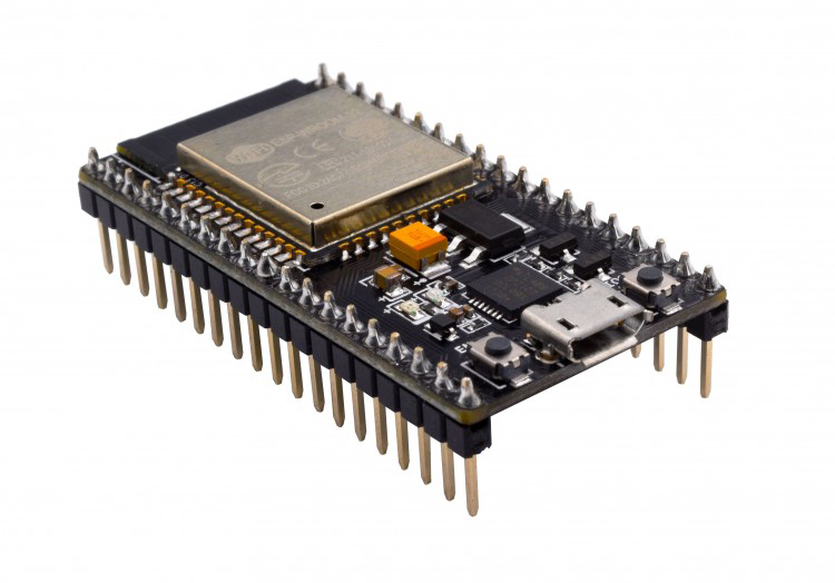
AI 3D tools can help makers explore enclosure shapes and layouts, but the final Arduino enclosure should be rebuilt in CAD using verified board dimensions, clearances, and tolerances.
Getting an Arduino or ESP32 project working on a breadboard is often the exciting part. The sensor responds, the display shows the right values, the motor turns, and the code finally behaves the way it should.
Then comes a less glamorous question:
What are you going to put everything in?
For many hobby projects, jumper wires and an exposed development board are perfectly fine during testing. But once a project needs to sit on a desk, hang on a wall, move around as a robot, or be shown to someone else, the enclosure becomes part of the design.
This is one area where AI-assisted 3D can help makers explore ideas before moving into precise CAD work and 3D printing.
Why the Enclosure Matters More Than It Seems
Consider a simple ESP32 air-quality monitor.
The electronics may include an ESP32 board, a small OLED display, a temperature or gas sensor, a USB connector, and perhaps a buzzer or status LED.
Electrically, the project may already be finished.
Physically, however, several decisions remain.
Where should the display sit? How much ventilation does the sensor need? Should the USB port be exposed on the side or rear? Will the enclosure stand on a desk or attach to a wall?
A plastic box with a few holes can solve the problem, but once the device will be used regularly, its physical layout affects usability.
A good enclosure does more than hide wires. It helps organize controls, protect electronics, provide ventilation, and make the project easier to understand.
Start With Function Before Appearance
Before generating or modeling anything, list the physical requirements of the project.
The enclosure needs enough space for the board, connectors, wiring, sensors, batteries, and mounting hardware. Parts that users need to reach should remain accessible.
A temperature sensor placed inside a sealed box may produce poor readings. A microphone needs an opening. A push button needs enough travel. A USB port cannot sit behind a thick wall.
These details should guide the design before styling begins.
Once those constraints are understood, the maker can start asking visual questions.
Should the enclosure look like a compact desktop instrument? Could it have rounded corners? Would a slightly angled front panel make the display easier to read?
These are areas where rapid 3D concept generation can be useful.
How Can AI 3D Help Design an Arduino Enclosure?
Traditional CAD is excellent when exact measurements matter, but it is not always the fastest environment for exploring several completely different visual directions.
Suppose you are building an ESP32 weather station.
You know that the final case needs a display on the front, ventilation openings, a USB connection, and enough internal volume for the board and sensors. But you have not decided what the device should actually look like.
You could explore several concepts first.
One version might resemble a small desktop clock. Another could use a vertical enclosure with the display angled upward. A third might have a more industrial look suitable for a workshop.
Platforms such as Meshy AI can create 3D models from written descriptions or visual references, giving makers a quick way to turn these rough ideas into something they can inspect from different angles.
At this stage, the model is not the final enclosure.
It is a design conversation.
How to Write an AI 3D Prompt for an Arduino Enclosure
When working from text, a useful prompt should describe what the object is supposed to do.
Instead of writing:
“Cool futuristic Arduino case”
provide functional information:
“Compact desktop enclosure for an ESP32 environmental monitor, rectangular body with rounded corners, small screen on the angled front panel, ventilation slots on both sides, USB opening at the rear, simple maker-project aesthetic.”
A text to 3D workflow can use that description to generate several possible forms.
The maker can then compare them and decide which overall direction is worth recreating more precisely in CAD.
This can save time because it separates two questions that are often mixed together:
What should the enclosure look like?
and
What exact dimensions does the enclosure need?
AI can help with the first question. CAD remains much better for the second.
When Should You Move an AI Enclosure Concept Into CAD?
Once the overall shape has been selected, measurements need to take over.
An Arduino Uno, ESP32 DevKit, Raspberry Pi Pico, sensor breakout board, or custom PCB has real dimensions that the enclosure must respect.
Mounting holes need correct spacing. USB connectors need clearance. Buttons need to align with openings. Walls need appropriate thickness, and screw posts need enough material around them.
These are not details that should be guessed from an AI-generated model.
Measure the real hardware or use reliable board drawings.
Then recreate or modify the chosen concept in a CAD tool where dimensions can be controlled precisely.
Think of the AI-generated model as a sketch in three dimensions. It can help establish shape and appearance, while CAD converts that idea into a manufacturable enclosure.
Plan for Wires and Connectors Early
One of the easiest mistakes is designing the case around the board but forgetting everything connected to it.
A development board may fit perfectly until jumper connectors, sensor cables, or a USB plug are added.
Leave space around headers and connectors.
If the device uses removable sensors, think about how they will be installed and replaced. If the enclosure contains a battery, consider how users will access it without dismantling the entire device.
Cable routing also affects the internal design.
Even a few Dupont wires can require more room than expected once the case is closed.
A quick physical mock-up using cardboard or a rough 3D print can reveal these problems before the final enclosure is produced.
Ventilation Can Be a Functional Feature
Many microcontroller projects include components that interact with the surrounding environment.
Temperature, humidity, gas, smoke, air-quality, and sound sensors all need some level of exposure.
That means openings should not be added only as decoration.
Their location should follow the sensor.
For example, if an air-quality sensor sits near one side of the PCB, ventilation slots around that region may help the sensor interact with ambient air more effectively.
At the same time, the enclosure should still protect the electronics from accidental contact.
The most successful designs make these functional requirements part of the visual language rather than treating them as holes added at the end.
Think About How the Project Will Be Used
A portable Arduino project needs a different enclosure from something permanently mounted to a wall.
A small robot needs room for motors, batteries, wheels, sensors, and wiring, while also keeping the center of gravity reasonable.
A desktop controller may need buttons positioned for frequent use.
A sensor node installed outdoors may require much more attention to weather resistance than a project that remains on a workbench.
Before finalizing the model, imagine the complete lifecycle of the device.
How will it be powered?
How will firmware updates be uploaded?
Can the case be opened again?
Can damaged components be replaced?
These questions often affect the enclosure more than visual styling does.
Test With a Rough Print Before the Final Version
3D printing makes iteration inexpensive, but there is still little reason to start with a perfect-looking print.
A fast draft print can answer the most important physical questions.
Does the board fit?
Are the ports aligned?
Can the lid close with the wires connected?
Are the buttons accessible?
Does the display sit at a comfortable angle?
If the answer to any of these is no, changing the CAD file and printing another rough version is much cheaper than discovering the problem after spending hours on a high-quality final print.
AI and CAD Solve Different Parts of the Problem
AI-generated 3D and traditional CAD should not be treated as competitors in this workflow.
They solve different problems.
AI is useful when a maker wants to explore form quickly, compare several enclosure concepts, or turn a rough description into something visible.
CAD becomes essential when the project reaches exact dimensions, tolerances, mounting points, and print preparation.
A practical workflow might therefore look like this:
idea → 3D concept exploration → selected enclosure direction → measured CAD model → test print → corrections → final enclosure.
The electronics remain at the center of the project.
The 3D workflow simply helps turn the working circuit into something that feels more complete.
Build the Box After You Understand the Project
It is tempting to design an enclosure as soon as a project begins, but hardware projects change constantly during development.
Sensors move. Boards are replaced. Batteries become larger. New buttons appear.
Waiting until the core circuit is stable prevents unnecessary redesign.
Once the electronics are working, however, enclosure design is worth taking seriously.
A well-designed case can make the difference between a breadboard experiment and a project that is comfortable to use, transport, demonstrate, or install.
AI 3D gives makers another way to explore what that case could look like before precision modeling begins.
Then CAD, measurement, testing, and 3D printing turn the idea into something that actually fits the hardware.
That combination makes sense for the same reason Arduino itself became popular: use the fastest tool for experimentation, then add precision when the project is ready for it.