Coaxial connectors provide a reliable way to transfer high-frequency electrical signals between cables, circuit boards, antennas, test equipment and other electronic hardware. Their construction follows the same principle as coaxial cable: a central conductor carries the signal, while a surrounding conductive shield provides the return path and reduces exposure to external electromagnetic interference. The connector maintains this geometry across the connection, helping preserve signal quality at radio-frequency (RF) and high-speed frequencies.
How Coaxial Connectors Work
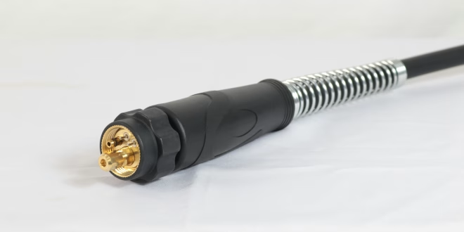
A typical coaxial connector contains a centre contact, dielectric insulation, an outer conductor and a mechanical coupling mechanism. The centre contact connects to the signal conductor, while the outer conductor joins the cable shield or circuit ground. Maintaining a consistent distance between these conductors is important because it determines the connector's characteristic impedance.
Many RF systems use 50-ohm impedance, while 75-ohm versions are common in video and telecommunications equipment. A mismatch between a cable, connector and circuit can cause reflections, increasing insertion loss and reducing the amount of signal reaching the receiver. At higher frequencies, even small changes in geometry can affect performance, which is why connector dimensions and manufacturing tolerances matter.
Connector Types and Their Applications
Several coaxial connector families are used across electronic and embedded systems. SMA connectors are compact and commonly found on RF modules, antennas and laboratory equipment. BNC connectors use a bayonet coupling mechanism and are frequently used for oscilloscopes, test instruments and video equipment. N-type connectors are larger and suited to applications such as outdoor antennas and communications infrastructure where mechanical strength and environmental resistance matter.
For compact embedded hardware, smaller options such as MMCX and MCX can reduce board and enclosure space. Designers can select from this range of coaxial connectors depending on the required frequency, impedance, mounting method and physical dimensions.
PCB-Mounted and Cable Connections
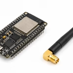
Coaxial connectors are not limited to cable-to-cable connections. PCB-mounted versions provide a direct interface between an RF circuit and an external cable or antenna. Board-edge SMA connectors, for example, can connect a transmission line on a PCB to an external RF cable without requiring a separate wire harness.
The PCB layout around the connector is part of the signal path. Ground vias placed near the connector, controlled transmission-line dimensions and a continuous ground reference help maintain the intended impedance. A poorly designed transition can introduce discontinuities even when the connector itself meets its specified electrical characteristics.
Selecting the Right Connector
Connector selection depends on more than physical compatibility. Frequency range, impedance, mating cycles, mounting style, cable type and environmental conditions all influence the choice. A connector rated for 6 GHz, for example, may not provide the same electrical performance at 18 GHz. Likewise, a board-mounted connector intended for a few hundred mating cycles may be unsuitable for equipment that is repeatedly connected during testing.
Mechanical factors also matter in embedded products. Right-angle connectors can simplify cable routing inside a compact enclosure, while threaded couplings can provide stronger retention where vibration is present. Locking and latching mechanisms may be preferable when accidental disconnection could interrupt a measurement or communication link.
Installation and Signal Integrity
Correct assembly has a direct effect on RF performance. Cable connectors must be terminated according to the manufacturer's dimensions so that the centre conductor, dielectric and shield remain correctly positioned. Excessive bending near the connector can also change cable geometry and introduce signal losses.
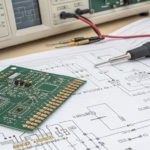
For prototype and production systems, engineers commonly verify connections with equipment such as a vector network analyser, measuring parameters including return loss and insertion loss. These measurements reveal whether the connector, cable and PCB transition are performing as intended across the operating frequency range. With suitable connector selection, accurate assembly and appropriate PCB design, coaxial interfaces can provide predictable connections throughout electronic and embedded systems.