A Schottky diode may look like a simple part, but it can have a noticeable effect on a low-voltage microcontroller circuit. In an ESP32 or Arduino-based design, a diode may be used for reverse-polarity protection, supply isolation, or preventing current from flowing back toward a USB or external power source.
The important question is not simply whether a diode can handle the current. Its forward-voltage drop, reverse-voltage rating, thermal behavior, and position in the circuit all matter.
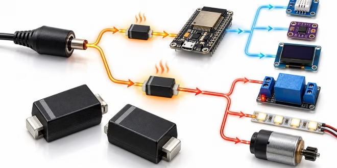
Consider a simple ESP32 controller powered like this:
5 V adapter → Schottky diode → 5 V/VIN rail → ESP32 board and sensors
If the board normally draws a few hundred milliamps but occasionally demands more when Wi-Fi and peripherals become active, the diode becomes part of the power-budget calculation.
Why Schottky Diodes Are Common in Microcontroller Power Paths
Compared with a conventional silicon rectifier, a Schottky diode typically has a lower forward-voltage drop. That is useful in low-voltage circuits because every fraction of a volt lost before the regulator reduces the available voltage margin.
A simple estimate of the power dissipated by the diode is:
P = I × VF
If the circuit draws 600 mA and the diode has a forward drop of 0.4 V at that operating point, it dissipates about 0.24 W. That may not sound like much, but in a small surface-mount package the junction temperature can rise noticeably, especially when PCB copper area is limited.
Forward voltage is not a fixed number. It changes with current and temperature, so the datasheet curve is more useful than relying only on the maximum value shown in a summary table.
When an SS14 Can Be a Good Fit
For many small microcontroller boards, the SS14 is a familiar starting point. A typical SS14 is rated around 1 A average forward current and 40 V repetitive peak reverse voltage in an SMA package.
In the ESP32 example, an SS14 Schottky diode can be appropriate when the diode is protecting or isolating the board-level supply and the expected current is relatively modest.
For example, if the ESP32 board and connected sensors normally remain well below 1 A, the SS14 may provide adequate electrical margin. But the “1 A” rating should not be treated as an automatic guarantee that the device can operate continuously at that current in every PCB layout.
Thermal performance depends on forward voltage, ambient temperature, copper area, airflow, and how heat is transferred through the pads. A sensible design checks both electrical rating and temperature rise.
When a Higher-Current Device Becomes Relevant
Now suppose the project changes. The ESP32 still consumes relatively little current, but the same input rail also supplies relays, a motor driver, or a larger LED load. The current passing through the power-path diode can then become much higher than the MCU current alone.
A higher-current part may make more sense in that situation. The SS56 Schottky diode referenced here is specified for 5 A average rectified current and 60 V repetitive peak reverse voltage in an SMA package.
That does not automatically make it a better choice for every ESP32 circuit.
| Parameter | SS14 | Linked SS56 |
| Average Forward Current | 1 A | 5 A |
| Reverse Voltage | 40 V | 60 V |
| Package | SMA | SMA |
| Typical Role in This Example | MCU board-level power path | Higher-current shared power path |
A higher current rating does not automatically make a Schottky diode a better choice for a low-current microcontroller power path. Forward drop, thermal behavior, physical package limits, cost, and actual circuit conditions still matter.
Component databases such as CNChipDepot can make the initial comparison faster, but the final choice should still come from the device datasheet and the conditions on the real board.
Check the Circuit, Not Just the Part Number
A practical Schottky diode selection starts with a few basic electrical questions.
What is the highest continuous current that will pass through the diode? What reverse voltage can appear across it? How much voltage drop can the downstream circuit tolerate? And how much heat can the PCB remove?
In a 5 V ESP32 power path, voltage drop may be more important than an especially high reverse-voltage rating. If the diode drops too much voltage, the regulator may have less input headroom, particularly when the external supply cable or connector already contributes additional loss.
Placement also matters. A diode used for reverse-polarity protection is operating under different conditions from a flyback diode across a relay coil or a rectifier in a switching power supply. The same Schottky diode should not be selected for all three applications simply because the footprint is convenient.
Measure the Result on the Real Board
Once the diode is installed, test the circuit at the expected load instead of relying only on calculations.
Measure the voltage before and after the diode while the board is operating normally. Then repeat the measurement when the ESP32 is transmitting over Wi-Fi or when connected peripherals are active. This reveals whether the diode and supply path are creating a significant voltage drop under peak load.
Temperature is equally important. Let the board run long enough to reach a stable operating temperature and check whether the diode is becoming excessively warm.
If the microcontroller resets when Wi-Fi starts, a relay activates, or another load turns on, examine the supply rail with an oscilloscope before assuming the problem is firmware. Excessive diode drop, inadequate supply headroom, or heating in the power path can create symptoms that look like software instability.
SS14 and SS56 make the point clearly: choosing a Schottky diode is not about finding the largest current rating that fits the footprint. It is about matching voltage drop, current capability, thermal behavior, and voltage margin to the circuit that will actually use it.