Your ESP32 can generate a perfectly stable PWM signal, yet a heater can still overshoot its target temperature, a motor can slow down under load, and a robot can struggle to follow a straight line. The microcontroller is doing exactly what you programmed it to do. It's the physical world that doesn't behave as predictably as your code.
Imagine trying to keep a small heater at 40 °C. Give it too much power, and the temperature climbs past the target. With too little, it takes too long to warm up or settles below the setpoint. The solution isn't simply switching the heater faster or adding more conditions to your code. You need a controller that continuously measures the result, calculates how far it is from the target, and adjusts the output accordingly. That is exactly what a PID controller does.
The ESP32 is well equipped for this job, but getting PID control right involves more than implementing three mathematical terms. Its ADC behaves differently from the Arduino Uno's, the LEDC peripheral generates the PWM, GPIO pins operate at 3.3 V, and other tasks can interfere with control-loop timing. Ignore these details, and even correctly written PID calculations can produce disappointing results. If you followed our Arduino PID Controller Tutorial, this is where the two boards part ways.
In this tutorial, we'll build an ESP32 PID temperature controller using an LM35 sensor, a MOSFET, and a small low-voltage heater. We'll implement the PID algorithm from scratch, improve its timing with FreeRTOS, compare it with the Arduino PID library, and work through practical tuning methods. Along the way, you'll learn how to handle sensor noise, output saturation, and hardware faults—techniques that apply just as well to motor speed control, robotics, and other feedback systems.
ESP32 PID Quick Start
Every PID controller repeats the same four steps. On the ESP32, each step maps to a function from the Arduino core.
| Step | What happens | ESP32 Arduino code |
|---|---|---|
| 1. Measure | Read the sensor | analogReadMilliVolts() |
| 2. Compare | Subtract the reading from the setpoint | error = setPoint - input |
| 3. Compute | Combine the P, I and D terms | computePID() or the PID library |
| 4. Act | Drive the actuator with PWM | ledcWrite() |
After step 4, the loop waits one sample period and then starts again. Step 3 implements this equation:

Here, e(t) is the error, while u(t) is the controller output. Kp, Ki and Kd are the three gains you will tune later.
What Is PID Control? A Quick Refresher
PID stands for Proportional, Integral, Derivative. It is a feedback method: the controller measures a value, compares it against a target called the setpoint, and adjusts an output to shrink the difference.
Three terms share the work:
- Proportional (P) reacts to the present error, so a bigger error produces a bigger push.
- Integral (I) adds up past error until it removes the small offset that P alone leaves behind, known as steady-state error.
- Derivative (D) watches how fast the reading changes and then eases off the output to reduce overshoot.
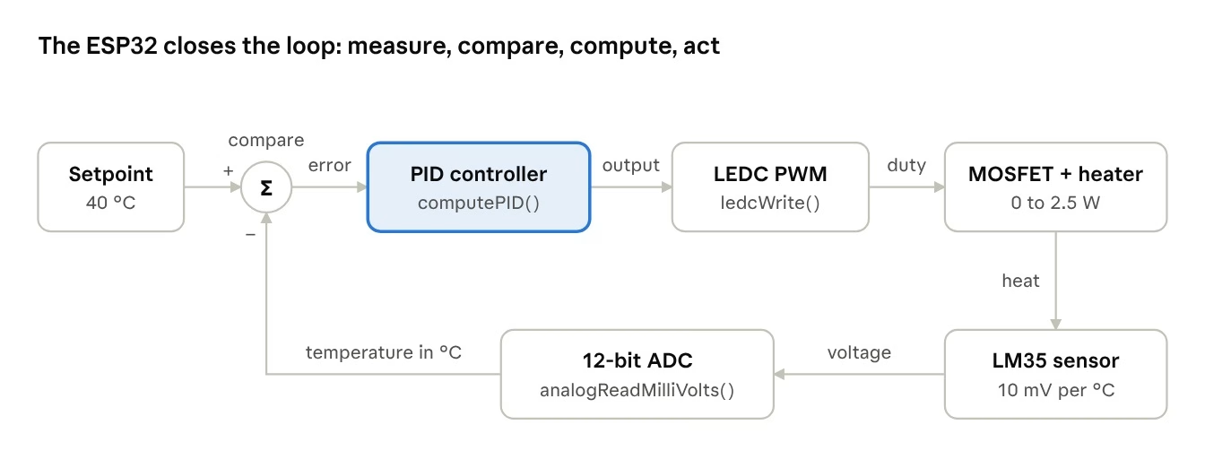
Follow the arrows from the setpoint. Each pass ends with a fresh sensor reading, which feeds the next comparison.
For more theory, the Arduino PID Controller Tutorial explains each term with a furnace example and shows how every gain shapes the response. From here on, we focus on the ESP32 side instead.
Arduino Uno vs. ESP32: What Changes for PID
Moving a PID controller from an Arduino Uno to an ESP32 leaves the equation untouched. The hardware around it is another story, as this table shows.
| Feature | Arduino Uno | ESP32 (ESP32-WROOM-32) |
|---|---|---|
| Logic level | 5 V | 3.3 V, and the pins are not 5 V tolerant |
| ADC | 10-bit, readings from 0 to 1023 | 12-bit, readings from 0 to 4095 |
| PWM | 8-bit analogWrite() at about 490 Hz or 980 Hz |
LEDC peripheral, frequency and resolution of your choice |
| Float math | Software only | Hardware FPU for float |
| Multitasking | A single loop() |
FreeRTOS on two cores |
| Wireless | None | Wi-Fi and Bluetooth |
What Each Difference Means for Your Controller
Each row has a practical consequence for your controller:
- 3.3 V logic. Sensor outputs must stay at or below 3.3 V, and the output stage must switch fully from a 3.3 V signal. Our guide to 3.3V vs 5V logic levels explains why.
- 12-bit ADC. Four times as many steps give you finer resolution. Resolution is not accuracy, though. The ESP32 ADC picks up noise and loses accuracy near both ends of its range, so the code below selects a suitable range and averages several samples.
- LEDC PWM. You choose both the frequency and the resolution. With 12 bits, the duty cycle runs from 0 to 4095 instead of 0 to 255.
- Hardware float. The ESP32 calculates float math in hardware, which makes a floating-point PID cheap. Only double still runs in software.
- FreeRTOS. A dedicated task can run the PID loop on a fixed schedule while
loop()handles printing or Wi-Fi.
Notice that the output range grows by a factor of about 16. Gains copied from an Arduino sketch will therefore feel far too weak, and the tuning section shows how to convert them.
This tutorial uses the classic ESP32 DevKit (see the ESP32 pinout diagram) and version 3.x of the ESP32 Arduino core. That core renamed the LEDC functions, so sketches that still call ledcSetup() or ledcAttachPin() need an update.
The same code also runs on the ESP32-S3 once you change the pin numbers to match the ESP32-S3 pinout. Chips without an FPU, such as the ESP32-C3, also work but compute floats in software.
The Example Circuit: A Small Temperature Controller
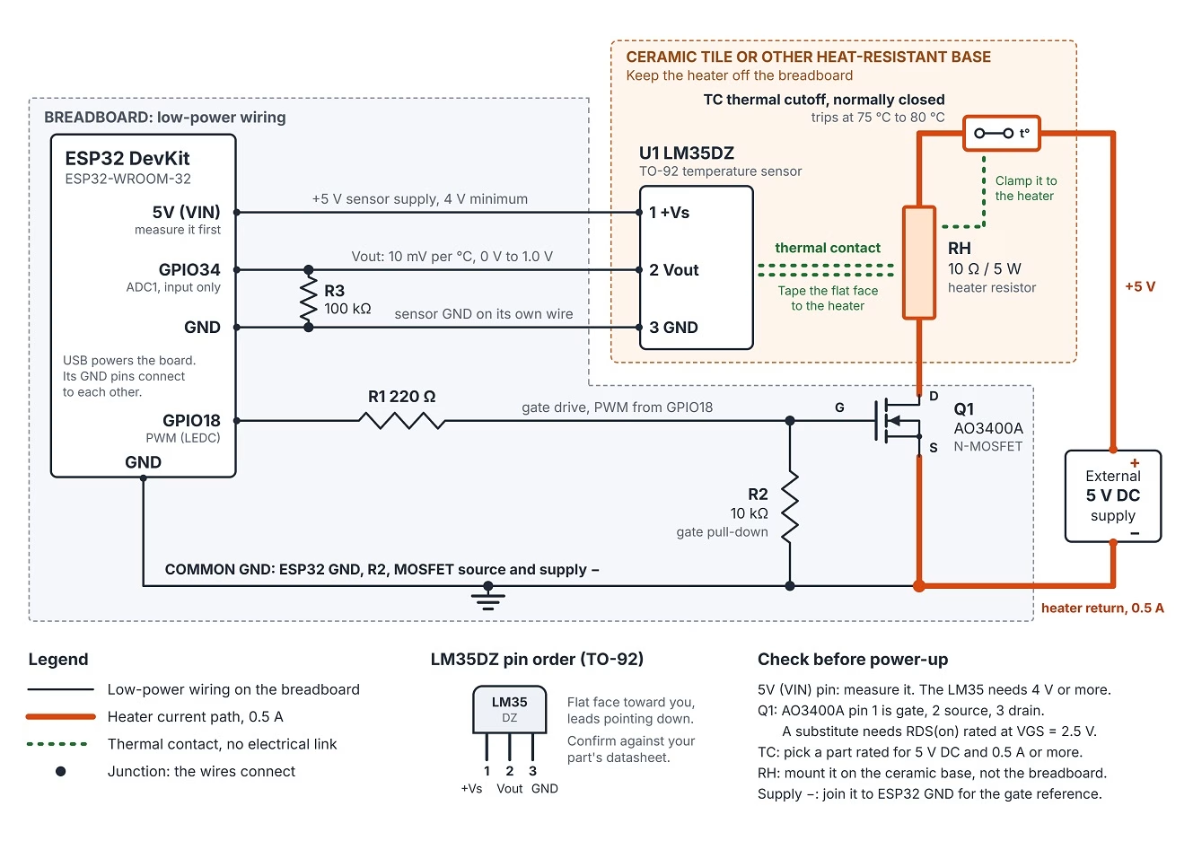
Every sketch in this tutorial controls the same circuit, which keeps the comparisons fair. An LM35 sensor measures the temperature of a small heater, while the ESP32 adjusts the heater power to hold a setpoint.
Treat this circuit as a learning rig. It demonstrates the feedback algorithm on real hardware, but it is not a finished temperature controller that you can leave running unattended.
You will need:
- ESP32 DevKit board with an ESP32-WROOM-32 module
- LM35DZ temperature sensor in a TO-92 package, rated for 0 °C to 100 °C
- Logic-level N-channel MOSFET that switches fully at 3.3 V
- Low-voltage heater, such as a 10 Ω, 5 W resistor
- Thermal cutoff, either a thermal fuse or a normally closed thermostat switch, with a trip point of about 75 °C to 80 °C and a rating that covers the heater's DC voltage and current
- External 5 V supply for the heater
- One 220 Ω, one 10 kΩ and one 100 kΩ resistor
- Breadboard and jumper wires for the low-power parts
- Ceramic tile or a similar heat-resistant base, plus heat-resistant polyimide tape
Wiring Connections
Wire the parts as follows:
| From | To | Purpose |
|---|---|---|
| LM35 +Vs | ESP32 5V (VIN) pin | Sensor supply |
| LM35 Vout | GPIO34 | Analog input on ADC1 |
| GPIO34 | GND, through 100 kΩ | Pulls the input low if the sensor wire breaks |
| LM35 GND | ESP32 GND | Sensor ground |
| GPIO18 | MOSFET gate, through 220 Ω | PWM signal |
| MOSFET gate | GND, through 10 kΩ | Holds the heater off during boot |
| MOSFET source | GND | Low-side switch |
| MOSFET drain | Heater, lower terminal | Switched load |
| Heater, upper terminal | Thermal cutoff, then external 5 V (+) | Heater supply through the cutoff |
| External 5 V (−) | ESP32 GND | Common ground |
 Circuit Details That Matter on an ESP32
Four details in this circuit matter on an ESP32:
- Sensor supply. The LM35 operates from 4 V to 30 V, so the 3.3 V pin cannot power it. Under normal operation, a 5 V supply is still compatible with the ESP32: the LM35DZ output rises by 10 mV per °C and stays between 0 V and 1.0 V across its rated 0 °C to 100 °C range. A wiring mistake can nevertheless put 5 V on GPIO34, so check the LM35 pin order before you apply power. On a USB-powered DevKit, the 5V pin normally carries the USB supply, but board designs differ, so measure the pin before you rely on it.
- Input pin. GPIO34 belongs to ADC1. The Wi-Fi driver takes over ADC2, which makes ADC2 pins unreliable once Wi-Fi starts.
- Pull-down resistor. GPIO34 has no internal pull resistors. Without the 100 kΩ resistor, a broken sensor wire leaves the pin floating, and a floating pin can then imitate a plausible temperature.
- MOSFET choice. Many "logic-level" MOSFETs still expect 4.5 V or 5 V at the gate. Pick a part whose datasheet specifies RDS(on) at a VGS of 2.5 V, such as the AO3400A on a breakout board (under 48 mΩ at 2.5 V).
Assemble the Heater Safely
A 10 Ω resistor across 5 V draws 0.5 A and dissipates 2.5 W. The 5 W rating only tells you that the resistor survives this load. Its surface can still get hot enough to burn skin, and a plastic breadboard is not made to hold hot parts.
Follow these four rules when you assemble the hot side of the circuit:
- Keep the heater off the breadboard. Mount the resistor on a ceramic tile or another heat-resistant, non-conductive base. Connect it with soldered wires or a screw terminal.
- Fix the sensor to the heater. Press the flat face of the LM35 against the resistor body and secure it with polyimide tape. A sensor that slips off is the most dangerous
faultin this project. - Add a cutoff that does not depend on the ESP32. Wire the thermal fuse or thermostat switch in series with the heater supply and clamp it firmly against the resistor, because it only works with good thermal contact. Choose a part that can interrupt the heater's DC voltage and current, here 5 V and 0.5 A. Should the software ever fail, the cutoff still opens the circuit.
- Stay with the circuit. Work with low voltage only, keep flammable material away, and switch the heater supply off whenever you leave the bench.
Good sensor contact also helps the control loop. A loose sensor adds delay, and delay makes any PID loop harder to tune.
If you would rather power the sensor from 3.3 V, a TMP36 works from 2.7 V to 5.5 V. Its output includes a 500 mV offset, so the conversion becomes (millivolts − 500) / 10. That higher output also calls for ADC_6db instead of ADC_0db in Step 2 below.
Implementing PID in ESP32 Code
Let's write the controller by hand first, because doing so reveals what a library hides.
The sketch relies on these variables:
| Variable | Role |
|---|---|
setPoint |
Target temperature in °C |
| input | Measured temperature in °C |
| output | PWM duty, from 0 to OUT_MAX |
| error | Setpoint minus input |
| integral | Running I term, already multiplied by Ki |
| derivative | Rate of change of the measurement, with the sign flipped |
previousInput |
Measurement from the previous cycle |
| Kp, Ki, Kd | Tuning gains |
dt |
Time since the last calculation, in seconds |
fault |
Set when a safety check fails, and kept until reset |
Step 1: Set Up the PWM Output
Start with the output stage, because the heater must stay off until the controller is ready.
const int PWM_PIN = 18;
const uint32_t PWM_FREQ = 5000;   // 5 kHz
const uint8_t  PWM_RES  = 12;     // 12-bit duty cycle

if (!ledcAttach(PWM_PIN, PWM_FREQ, PWM_RES)) {
  Serial.println("PWM setup failed. Check PWM_FREQ and PWM_RES.");
  while (true) {
    delay(1000);                  // stop here, the heater stays off
  }
}
ledcWrite(PWM_PIN, 0);            // heater off at startup
A single ledcAttach() call assigns a PWM channel to the pin and sets both frequency and resolution. It returns false when it cannot provide that combination, and the sketch then stops with the heater off. After a successful call, ledcWrite() accepts a duty value between 0 and 4095.
Frequency and resolution trade off against each other. On the classic ESP32, a 5 kHz signal supports up to 13 bits, so 12 bits fits comfortably.
Step 2: Read the Sensor
Next, the controller needs a clean temperature reading.
// In setup(): select the 100 mV to 950 mV input range
analogSetPinAttenuation(SENSOR_PIN, ADC_0db);

float readTemperature() {
  uint32_t sum = 0;
  for (int i = 0; i < 16; i++) {
    sum += analogReadMilliVolts(SENSOR_PIN);
  }
  float millivolts = sum / 16.0f;
  return millivolts / 10.0f;      // LM35: 10 mV per degree C
}
Three ESP32 habits appear in this code:
- Attenuation selects the input range. At 0 dB, Espressif rates the ESP32 ADC from 100 mV to 950 mV, which suits an LM35 between 10 °C and 95 °C. The default 11 dB setting starts at 150 mV instead. Base the choice on the full voltage range you expect, not only on the setpoint.
- analogReadMilliVolts() applies the factory calibration. It corrects for differences between chips. Noise, sensor error and the remaining ADC nonlinearity still affect the reading.
- Averaging removes part of the noise. The loop therefore takes 16 readings and returns their mean.
Step 3: Measure the Time Step
Both the integral and the derivative depend on time, so the sketch measures how long each cycle takes.
unsigned long currentTime = millis();

if (currentTime - previousTime >= SAMPLE_MS) {
  float dt = (currentTime - previousTime) / 1000.0f;   // seconds
  previousTime = currentTime;
  // read, check, compute and write here
}
This if statement runs the PID code every 100 ms without blocking loop(). Because dt comes from the real elapsed time, the math stays correct even when a cycle arrives late.
Step 4: Calculate the Three Terms
With a reading and a time step in hand, the three terms follow from the equation.
error = setPoint - measured;

derivative = -(measured - previousInput) / dt;
previousInput = measured;

float candidate = integral + Ki * error * dt;
candidate = constrain(candidate, OUT_MIN, OUT_MAX);
Notice that the derivative uses the measurement instead of the error. While the setpoint holds still, both versions give the same value. A setpoint change, however, makes the error jump in a single step, and a derivative taken from the error would spike. Engineers call that spike derivative kick.
The integral appears here as a candidate only, and the next step decides whether the controller accepts it. Because the candidate already includes Ki, it can share the output limits.
Step 5: Limit Integral Windup
Before the sketch commits the candidate, it checks what the output would look like.
float unclamped = Kp * error + candidate + Kd * derivative;

bool pushingHigh = (unclamped > OUT_MAX) && (error > 0.0f);
bool pushingLow  = (unclamped < OUT_MIN) && (error < 0.0f);
if (!pushingHigh && !pushingLow) {
  integral = candidate;
}

float result = Kp * error + integral + Kd * derivative;
return constrain(result, OUT_MIN, OUT_MAX);
Integral windup occurs when the output is saturated while the integral keeps growing. Picture the heater at its output limit during warm-up. The error stays positive, the integral piles up, and the surplus later holds the heater on after the temperature has reached the setpoint.
Two measures work together against it. Conditional integration keeps the previous integral whenever the new one would saturate the output and the error pushes further in that direction. The constrain() call from Step 4 then bounds whatever does accumulate. Clamping by itself only limits windup and does not prevent it.
Finally, the last two lines calculate the output from the accepted integral, so the result always reflects the current cycle.
Step 6: Check for Faults Before Driving the Heater
A heater controller must assume that its sensor can fail. For that reason, the sketch checks every reading before it calculates a new output.
input = readTemperature();
checkSafety(input);

if (fault) {
  output = 0.0f;              // heater stays off until reset
} else {
  output = computePID(input, dt);
}
ledcWrite(PWM_PIN, (uint32_t)output);
checkSafety() looks for three warning signs:
- A reading below 10 °C or above 70 °C
- A jump of more than 5 °C between two samples
- An output that stays at its limit for more than two minutes
Any of them sets fault, and the heater then stays off until you reset the board.
A broken sensor wire falls under the first check, since the 100 kΩ pull-down drags an open input below the 10 °C limit.
The third check is a timeout on continuous operation at the output limit. It does not measure whether the heater actually warms up, which leaves two gaps. A healthy heater that needs more than two minutes at the limit trips the timeout, and a detached sensor escapes it whenever the controller stays below OUT_MAX.
Detecting a real lack of heating takes more. The code would have to compare the temperature rise over a set interval while the heater receives significant power. Until you add such a check, treat the timeout as a backstop only.
These checks reduce the risk without removing it. The ESP32 that runs them can crash or hang, which is why the circuit also includes a cutoff that works without the microcontroller.
Complete ESP32 PID Sketch
Here is the full sketch with all six steps in place:
// ESP32 PID temperature controller - manual implementation
// Written for ESP32 Arduino core 3.x

const int SENSOR_PIN = 34;        // LM35 output, ADC1
const int PWM_PIN    = 18;        // MOSFET gate

const uint32_t PWM_FREQ = 5000;   // 5 kHz
const uint8_t  PWM_RES  = 12;     // 12-bit duty cycle, 0 to 4095
const float    PWM_FULL = 4095.0f;

// Output limits. Start with a 50% cap. Raise OUT_MAX toward 4095
// once the sensor and the safety checks have proven themselves.
const float OUT_MIN = 0.0f;
const float OUT_MAX = 2047.0f;

const uint32_t SAMPLE_MS = 100;   // PID sample time

// Safety limits - adjust them for your heater
const float    TEMP_MIN = 10.0f;           // below this, suspect the sensor
const float    TEMP_MAX = 70.0f;           // above this, shut down
const float    MAX_STEP = 5.0f;            // largest believable change per sample
const uint32_t MAX_SATURATED_MS = 120000;  // longest continuous time at OUT_MAX

// Illustrative gains - not tuned for your heater
float Kp = 300.0f;
float Ki = 5.0f;
float Kd = 0.0f;

float setPoint = 40.0f;           // target temperature in degrees C
float input  = 0.0f;
float output = 0.0f;

float error = 0.0f;
float integral = 0.0f;
float derivative = 0.0f;
float previousInput = 0.0f;

bool fault = false;               // latched until reset
unsigned long saturatedSince = 0;
unsigned long previousTime = 0;

float readTemperature() {
  uint32_t sum = 0;
  for (int i = 0; i < 16; i++) {
    sum += analogReadMilliVolts(SENSOR_PIN);
  }
  float millivolts = sum / 16.0f;
  return millivolts / 10.0f;      // LM35: 10 mV per degree C
}

// Sets the fault flag when a reading or the heater behavior looks wrong
void checkSafety(float measured) {
  // Reading outside the believable range
  if (measured < TEMP_MIN || measured > TEMP_MAX) fault = true;

  // Reading jumped faster than a heater can change
  if (fabsf(measured - previousInput) > MAX_STEP) fault = true;

  // Output held at its limit for too long
  if (output < OUT_MAX) {
    saturatedSince = millis();
  } else if (millis() - saturatedSince > MAX_SATURATED_MS) {
    fault = true;
  }
}

float computePID(float measured, float dt) {
  error = setPoint - measured;

  // Derivative on the measurement avoids derivative kick
  derivative = -(measured - previousInput) / dt;
  previousInput = measured;

  // Candidate integral for this cycle
  float candidate = integral + Ki * error * dt;
  candidate = constrain(candidate, OUT_MIN, OUT_MAX);

  // Conditional integration: keep the old integral while the output
  // would saturate and the error pushes it further into saturation
  float unclamped = Kp * error + candidate + Kd * derivative;
  bool pushingHigh = (unclamped > OUT_MAX) && (error > 0.0f);
  bool pushingLow  = (unclamped < OUT_MIN) && (error < 0.0f);
  if (!pushingHigh && !pushingLow) {
    integral = candidate;
  }

  float result = Kp * error + integral + Kd * derivative;
  return constrain(result, OUT_MIN, OUT_MAX);
}

void setup() {
  Serial.begin(115200);

  if (!ledcAttach(PWM_PIN, PWM_FREQ, PWM_RES)) {
    Serial.println("PWM setup failed. Check PWM_FREQ and PWM_RES.");
    while (true) {
      delay(1000);                // stop here, the heater stays off
    }
  }
  ledcWrite(PWM_PIN, 0);          // heater off at startup

  analogSetPinAttenuation(SENSOR_PIN, ADC_0db);   // 100 mV to 950 mV range

  previousInput = readTemperature();
  previousTime = millis();
  saturatedSince = millis();
}

void loop() {
  unsigned long currentTime = millis();

  if (currentTime - previousTime >= SAMPLE_MS) {
    float dt = (currentTime - previousTime) / 1000.0f;   // seconds
    previousTime = currentTime;

    input = readTemperature();
    checkSafety(input);

    if (fault) {
      output = 0.0f;              // heater stays off until reset
    } else {
      output = computePID(input, dt);
    }
    ledcWrite(PWM_PIN, (uint32_t)output);

    // Label:value pairs for the Serial Plotter
    Serial.printf("Setpoint:%.1f,Temperature:%.2f,OutputPercent:%.1f,Fault:%d\n",
                  setPoint, input, output * 100.0f / PWM_FULL, fault);
  }
}
A few lines deserve a comment:
- The gains are illustrative. Nobody has tuned Kp = 300, Ki = 5 and Kd = 0 for your heater. From a 25 °C start, the proportional term alone asks for 300 × 15 = 4500, so the controller begins at its output limit.
- Kd starts at zero. The example therefore runs as a PI controller, and the derivative term has no effect on the output yet. Many slow thermal systems work well that way. Introduce Kd after you have tuned Kp and Ki, and only if the response needs more damping.
- OUT_MAX starts at half power. A cap of 2047 holds the heater to 50% duty while you confirm that the sensor and the safety checks work. Raise it toward 4095 afterward.
- setup() seeds previousInput. Without that line, the first cycle would see a jump from zero and trip the step check at once.
- The print statement targets the Serial Plotter. Each Label:value pair becomes a named trace, and Fault moves from 0 to 1 when a check trips.
First Power-Up
Test the sensor and the fault handling before you trust the heater:
- Leave the heater supply unplugged, upload the sketch, and open Tools > Serial Plotter at 115200 baud. The temperature trace should then match the room.
- Warm the LM35 between your fingers until the trace rises by a few degrees.
- Let go of the sensor and wait about two minutes. An unplugged heater cannot raise the temperature, so the output-limit timeout should set Fault to 1. Reset the board.
- Pull the sensor wire from GPIO34. Fault should jump to 1 at once. Reconnect the wire and reset the board again.
- Plug in the heater supply and watch the first warm-up from start to finish.
With a correctly wired circuit and suitable gains, the temperature should rise toward the setpoint, and the output should decrease as the temperature approaches it. The actual curve still depends on your heater, the sensor placement and the gains.
Does Fault trip during a normal warm-up? Your heater then needs more than two minutes at the output cap. Increase MAX_SATURATED_MS, but only as far as the warm-up requires.
Running the PID Loop in a FreeRTOS Task
The manual sketch works, but its timing depends on everything else inside loop(). Add a Wi-Fi reconnect or a slow display update, and the 100 ms interval starts to wander.
Fortunately, the ESP32 offers a better home for the controller. Your sketch already runs on FreeRTOS, and loop() itself is a FreeRTOS task. Nothing stops you from creating a second task that handles only the PID loop.
Why not use a hardware timer interrupt instead? Interrupt handlers must stay short, and Espressif's ADC driver warns against calling its read function from one. A task, in contrast, has neither limit.
Keep everything above setup() from the manual sketch. Then replace setup() and loop() with this code:
// One complete result from a single PID cycle
struct PidSample {
  float temperature;
  float output;
  bool  fault;
};

QueueHandle_t sampleQueue;        // carries the newest sample to loop()

void pidTask(void *parameter) {
  const TickType_t period = pdMS_TO_TICKS(SAMPLE_MS);
  TickType_t lastWakeTime = xTaskGetTickCount();
  uint32_t lastMicros = micros();

  for (;;) {
    vTaskDelayUntil(&lastWakeTime, period);             // wait for the next slot

    uint32_t nowMicros = micros();
    float dt = (nowMicros - lastMicros) / 1000000.0f;   // measured, in seconds
    lastMicros = nowMicros;

    input = readTemperature();
    checkSafety(input);
    output = fault ? 0.0f : computePID(input, dt);
    ledcWrite(PWM_PIN, (uint32_t)output);

    PidSample sample = { input, output, fault };
    xQueueOverwrite(sampleQueue, &sample);              // keep only the newest
  }
}

void setup() {
  Serial.begin(115200);

  if (!ledcAttach(PWM_PIN, PWM_FREQ, PWM_RES)) {
    Serial.println("PWM setup failed. Check PWM_FREQ and PWM_RES.");
    while (true) {
      delay(1000);                // stop here, the heater stays off
    }
  }
  ledcWrite(PWM_PIN, 0);          // heater off at startup

  analogSetPinAttenuation(SENSOR_PIN, ADC_0db);   // 100 mV to 950 mV range

  previousInput = readTemperature();
  saturatedSince = millis();

  sampleQueue = xQueueCreate(1, sizeof(PidSample));

  BaseType_t created = pdFAIL;
  if (sampleQueue != NULL) {
    created = xTaskCreatePinnedToCore(
      pidTask,       // task function
      "PID Task",    // task name
      4096,          // stack size in bytes
      NULL,          // parameter
      2,             // priority, above loop()
      NULL,          // task handle
      1);            // core 1
  }

  if (created != pdPASS) {
    Serial.println("PID task did not start. The heater stays off.");
    while (true) {
      delay(1000);
    }
  }
}

void loop() {
  PidSample sample;

  // Wait up to one second for the next sample from the PID task
  if (xQueueReceive(sampleQueue, &sample, pdMS_TO_TICKS(1000)) == pdTRUE) {
    Serial.printf("Setpoint:%.1f,Temperature:%.2f,OutputPercent:%.1f,Fault:%d\n",
                  setPoint, sample.temperature,
                  sample.output * 100.0f / PWM_FULL, sample.fault);
  } else {
    Serial.println("No data from the PID task");
  }
}
How the FreeRTOS Version Works
Several choices in this code deserve an explanation:
- vTaskDelayUntil() sets the schedule. It wakes the task every 100 ms, counted from the previous wake-up. Time spent reading the sensor therefore does not stretch the cycle.
- The task still measures dt. A schedule is not a guarantee, though. When a cycle overruns or a higher-priority task holds the CPU,
vTaskDelayUntil()returns late, or it does not wait at all. Timing every cycle withmicros()keeps the integral and the derivative correct in those cases. - A queue carries the results. The PID task packs temperature, output and
faultstate into one PidSample. Since the queue holds a single item,xQueueOverwrite()always replaces it with the newest sample, andloop()receives a set of values from the same cycle. Plain global variables give no such guarantee across two tasks, even with the volatile keyword. - Priority 2 beats loop(). The Arduino core runs
loop()at priority 1. Whenever the PID task is due, FreeRTOS pausesloop()and runs the controller first. - Core 1 avoids the radio. By default, the Wi-Fi driver lives on core 0, so the PID task stays out of its way on core 1.
- setup() checks its own work. Creating the queue or the task can fail when memory runs short. The sketch then reports the problem and never switches the heater on.
Working Alongside the PID Task
With this structure, loop() is free for slow jobs. Printing, a web page or an MQTT client can then run there without disturbing the control timing.
The same rule applies in the other direction. If loop() later changes the setpoint or the gains while the task runs, send those values through a second queue instead of writing the globals directly.
One limit remains: the Arduino core sets the FreeRTOS tick to 1 ms, so a task period cannot go below that. Temperature control never needs such speed, although fast motor loops sometimes do.
To learn more about tasks, priorities and queues, read our ESP32 FreeRTOS tutorial.
Using the PID Library on ESP32
Maintaining the math yourself is optional. The Arduino PID Library by Brett Beauregard, known as PID_v1, also runs on the ESP32. It is the same library the Arduino tutorial uses, so the functions will look familiar.
To install it, open Sketch > Include Library > Manage Libraries, search for "PID", and install the entry by Brett Beauregard. Then upload this sketch to the same circuit:
// ESP32 PID temperature controller - PID library version
// Written for ESP32 Arduino core 3.x

#include <PID_v1.h>

const int PIN_INPUT  = 34;        // LM35 output, ADC1
const int PIN_OUTPUT = 18;        // MOSFET gate

const double OUT_MAX  = 2047;     // 50% cap for first tests, full scale is 4095
const double TEMP_MIN = 10.0;     // below this, suspect the sensor
const double TEMP_MAX = 70.0;     // above this, shut down

const unsigned long SAMPLE_MS = 100;

double Setpoint, Input, Output;

// Illustrative gains - not tuned for your heater
double Kp = 300, Ki = 5, Kd = 0;

PID myPID(&Input, &Output, &Setpoint, Kp, Ki, Kd, DIRECT);

bool fault = false;               // latched until reset
unsigned long lastSample = 0;

double readTemperature() {
  uint32_t sum = 0;
  for (int i = 0; i < 16; i++) {
    sum += analogReadMilliVolts(PIN_INPUT);
  }
  return (sum / 16.0) / 10.0;     // LM35: 10 mV per degree C
}

void setup() {
  Serial.begin(115200);

  if (!ledcAttach(PIN_OUTPUT, 5000, 12)) {   // 5 kHz, 12-bit
    Serial.println("PWM setup failed. Check frequency and resolution.");
    while (true) {
      delay(1000);                    // stop here, the heater stays off
    }
  }
  ledcWrite(PIN_OUTPUT, 0);           // heater off at startup

  analogSetPinAttenuation(PIN_INPUT, ADC_0db);   // 100 mV to 950 mV range

  Setpoint = 40.0;                    // degrees C
  Input = readTemperature();
  lastSample = millis();

  myPID.SetOutputLimits(0, OUT_MAX);  // the library default is 0 to 255
  myPID.SetSampleTime(SAMPLE_MS);     // milliseconds
  myPID.SetMode(AUTOMATIC);
}

void loop() {
  unsigned long now = millis();

  // Sample the sensor on a fixed schedule
  if (now - lastSample >= SAMPLE_MS) {
    lastSample = now;
    Input = readTemperature();

    if (!fault && (Input < TEMP_MIN || Input > TEMP_MAX)) {
      fault = true;
      myPID.SetMode(MANUAL);          // stop the controller
      Output = 0;
      ledcWrite(PIN_OUTPUT, 0);       // heater stays off until reset
      Serial.println("Fault: reading out of range. Heater off.");
    }
  }

  // Compute() does the math once per sample time and then returns true
  if (!fault && myPID.Compute()) {
    ledcWrite(PIN_OUTPUT, (uint32_t)Output);

    Serial.printf("Setpoint:%.1f,Temperature:%.2f,OutputPercent:%.1f\n",
                  Setpoint, Input, Output * 100.0 / 4095.0);
  }
}
Compared with an Arduino Uno sketch, only a handful of lines change:
- SetOutputLimits() is essential. The library limits its output to 0 through 255 by default. Skip this call, and the heater never rises above roughly 6% power.
- ledcAttach() and ledcWrite() replace analogWrite(). They also give the output its 12-bit range.
- The sensor follows its own schedule. Reading it on every pass through
loop()would waste 16 conversions each time. Instead, the sketch samples every 100 ms, andCompute()picks up the newest value. - Compute() tells you when to act. It returns true once per sample time, so the sketch updates the PWM pin only when a fresh output exists.
- A fault stops the library as well. Switching to MANUAL mode halts the calculation, and the sketch forces the output to zero.
- DIRECT suits a heater. More output raises the temperature. For a cooling fan, where more output instead lowers the reading, choose REVERSE.
Notice that the library works with double variables. The ESP32 FPU accelerates only float, so these calculations run in software. At ten updates per second, however, you will not notice the difference.
Manual PID Code vs. the PID Library
The library and the handwritten controller differ in more than their length, as this table shows.
| Aspect | Manual code | PID library |
|---|---|---|
| Math type | float, hardware accelerated | double, in software |
| Time step | Measured in every cycle | Taken from the configured sample time |
| Anti-windup | Conditional integration plus a clamp | Clamp on the integral sum |
| Derivative | From the measurement | From the measurement |
| Safety checks | Three checks in checkSafety() |
Range check only in this example |
| Extras | Only what you add | Manual and automatic modes, direction setting |
To keep the library example short, it carries only the range check. As it stands, it therefore offers less protection than the manual sketch. Copy checkSafety() over when you want all three checks.
For learning and for tight control over timing, the manual version wins. When you simply want a working loop, the library gets you there faster.
How to Tune Your ESP32 PID Controller
A PID controller is only as good as its gains. The tuning process on an ESP32 matches the one in the Arduino tutorial, but with a larger output range to keep in mind.
Manual Tuning in Three Stages
Watch the Serial Plotter while you work through these stages:
- Kp first. Set Ki and Kd to zero. Raise Kp gradually until the temperature responds quickly without sustained oscillation.
- Ki second. If the temperature settles slightly below the setpoint, add Ki in small steps until the gap closes. Too much Ki produces overshoot and slow, repeated swings.
- Kd last, if needed. A little Kd can damp overshoot, but it also amplifies sensor noise. Many temperature loops run well with Kd at zero.
Change one gain at a time, and give a slow system such as a heater a minute or two to show its response. Repeat the check whenever you raise OUT_MAX, because a higher limit lets the heater push harder.
A Faster Start with the PID Tuning Calculator
Guessing gains takes patience. Our PID Tuning Calculator shortens the search by applying the Ziegler-Nichols closed-loop method to two measurements:
- Set Ki and Kd to zero.
- Raise Kp gradually until the temperature oscillates steadily around the setpoint. That Kp value is the ultimate gain, Ku.
- Measure the time between two neighboring peaks in the Serial Plotter. This is the oscillation period, Tu.
- Enter Ku and Tu into the calculator, choose P, PI or PID, and read off Kp, Ki and Kd.
Expect the temperature to swing above the setpoint during this test, and choose a modest setpoint for that reason.
Suppose the temperature oscillates steadily at Kp = 800 with 20 seconds between peaks. For a PI controller, the calculator then suggests Kp = 360 and Ki = 21.6.
Since you measured Ku on the ESP32 itself, the results already suit the 12-bit output. Both the manual sketch and PID_v1 use a time base in seconds for their integral and derivative calculations. Enter Tu in seconds so that the calculated gains match these implementations.
Two cautions apply. The calculator also prints a PID_v1 snippet for Arduino, so remember to keep your own SetOutputLimits() call and ledcWrite() when you paste it into an ESP32 sketch. Ziegler-Nichols gains also tend to be aggressive, so treat them as a baseline and refine them on the real system.
Reusing Gains from an Arduino Sketch
If you already tuned the same hardware on an Arduino Uno, you can carry those gains over with one multiplication. This shortcut holds only while everything else stays comparable: the same heater and supply, a PID input in physical units such as °C, the same form of the PID equation, and Ki and Kd in the same time units.
The Uno's analogWrite() spans 0 to 255, while a 12-bit LEDC channel spans 0 to 4095. Multiply Kp, Ki and Kd by 4095 / 255, or roughly 16, to command the same duty cycle for the same error.
For example, the temperature project in the Arduino tutorial uses Kp = 2.0, Ki = 0.5 and Kd = 1.0. Scaled for a 12-bit output, those become about Kp = 32, Ki = 8 and Kd = 16.
The conversion also assumes that the new output limits allow the same duty range. With the initial 50% cap in the example sketches, the controller cannot reproduce commands that used to exceed 50% duty.
Even so, converted gains remain a starting point. A different heater, supply voltage or sensor position shifts the ideal values, which is why the sketches above carry their own example gains.
There are two ways around the conversion:
- Switch the output back to 8 bits. Set
PWM_RESto 8 and bothPWM_FULLandOUT_MAXto 255, and the old gains apply again. - Retune from scratch, which is the only safe route if the old sketch fed raw
analogRead()counts into the PID. One count means about 4.9 mV on a Uno but only about 0.8 mV on an ESP32 at the default attenuation.
ESP32 PID Troubleshooting
When the response looks wrong, check the hardware and the setup before you touch the gains. This table lists the problems that are specific to the ESP32.
| Symptom | Likely cause | What to try |
|---|---|---|
| Heater barely warms with the library | Output limits still at 0 to 255 |
Call SetOutputLimits() with your 12-bit limits |
| Ported Arduino gains feel far too weak | Gains sized for an 8-bit output | Multiply them by about 16 |
| Readings freeze or fail when Wi-Fi starts | Sensor wired to an ADC2 pin | Move it to GPIO32 through GPIO39 |
| Low temperatures read wrong | Sensor voltage below the rated ADC range | Match the attenuation to the sensor, or switch to a TMP36 |
Output jitters although the temperature is steady |
Kd amplifies ADC noise | Lower Kd or filter the reading |
| PWM pin stays silent | Frequency and resolution do not fit together | Lower one of them and check what ledcAttach() returns |
| Board fails to boot with the MOSFET connected | Gate circuit on a strapping pin | Avoid GPIO0, GPIO2, GPIO5, GPIO12 and GPIO15 |
| Fault trips during a normal warm-up | Warm-up at the output cap outlasts the timeout | Increase MAX_SATURATED_MS or OUT_MAX with care |
| Temperature runs away from the setpoint | Wrong error sign or direction | Check setPoint - measured, or DIRECT versus REVERSE |
General symptoms such as slow response or steady oscillation behave the same on every board. For those, turn instead to the troubleshooting table in the Arduino tutorial.
Two rows of the table need more background.
Filtering Without Upsetting the LM35
Espressif suggests a 0.1 µF capacitor at the ADC pin to reduce noise. The LM35, however, can drive only about 50 pF by itself. Place a 2 kΩ resistor between the sensor output and the capacitor, as the LM35 datasheet shows.
Software offers further options. Our guide to sensor reading filtering compares several filters you can add to readTemperature().
Matching PWM Frequency and Resolution
On the classic ESP32, the Arduino core clocks the LEDC timer from 80 MHz. The frequency multiplied by the number of duty steps therefore cannot exceed 80,000,000. A heater is content with 5 kHz and 12 bits, whereas a motor at 20 kHz gets 11 bits at most, which means a duty range of 0 to 2047.
Other chips have different limits. On variants such as the ESP32-S3, the core selects the 40 MHz crystal as the LEDC clock, and the product of frequency and steps drops by half.
ESP32 PID FAQs
What sample time should I use?
Match it to the speed of your system. A small heater changes slowly, so anything from 100 ms to 1 s is fast enough, while motor speed loops usually need 20 to 100 ms. The sample time table in the Arduino PID tutorial lists more starting points.
Can I use analogWrite() instead of the LEDC functions?
You can. On the ESP32, analogWrite() drives the same LEDC hardware with 8-bit resolution at 1 kHz by default. Calling ledcAttach() yourself, however, gives you control over both settings.
Does this code run on the ESP32-S3 or ESP32-C3?
The ESP32-S3 needs new pin numbers and a look at the PWM limits above. Single-core chips such as the ESP32-C3 have no core 1, so create the task with xTaskCreate() there. Expect slower float math on the C3 as well, because it lacks an FPU.
Can I leave this heater controller running unattended?
No. These sketches teach the algorithm, but their safety checks cover only the most obvious faults. Anything that runs unattended needs independent overtemperature protection, construction suited to the heat, and fault handling that you have tested on the real hardware.
Conclusion
The PID equation is the same on every microcontroller. On the ESP32, however, the work lies in the details around it:
- Read the sensor on an ADC1 pin with
analogReadMilliVolts(), choose a matching attenuation, and then average the samples. - Drive the load with
ledcAttach()andledcWrite(), and size the output limits and the gains for the PWM resolution. - Pause the integral while the output is saturated, and take the derivative from the measurement.
- Give the loop its own FreeRTOS task, measure
dt, and pass the results through a queue. - Shut the heater down on implausible readings, and also back the software up with a hardware cutoff.
Because loop() is now free, the ESP32 can report the temperature over Wi-Fi. Our tutorial on showing sensor data on an ESP32 web server is a good place to start.
References
- Espressif Arduino-ESP32 LEDC API
- Espressif Arduino-ESP32 ADC API
- Texas Instruments LM35 datasheet
- Alpha & Omega Semiconductor AO3400A datasheet
- Arduino PID Library by Brett Beauregard (PID_v1)