
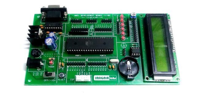
The 8051 microcontroller is much older than the ones featured here. Yes, even older than the PIC16F84A. However, being flooded by messages from students about this microcontroller tells me that universities still teach it. Hence, in line with our goal to teach microcontrollers to anyone, we decided to add the 8051 to our lineup.
The first part of this tutorial series shows how to start programming with the 8051 using Keil's C51 compiler. Here you'll learn how to flash an LED and use a switch.
Setting Up
- Download and install Keil for 8051
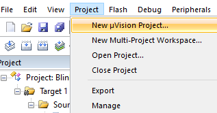
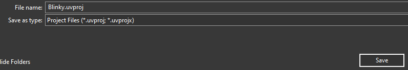
- Open Keil, create a new project and name it. Here, we name the project Blinky.
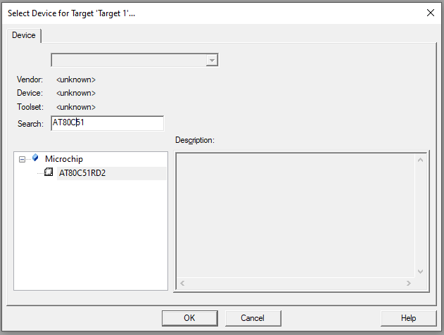
- At this point, you can select any 8051 derivatives. We limit ourselves to those found in Proteus ISIS. One of them is AT80C51RD2 and so we select it.
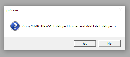
- A dialog will ask you about including the STARTUP.A51 file which does the register aliasing for us. Naturally, choose Yes.
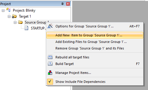
- Each project requires one main.c file. To add such file, right-click on Source Group 1 folder, select Add New Item...
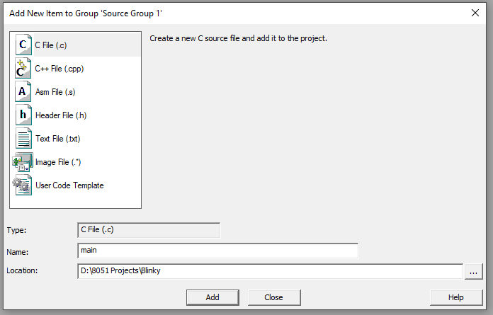
- Select .c file extension and name the file main.c
- At this point we can start coding. For first-timers, I suggest you paste the following code to main.c and save. The explanation of this code comes in the later section.
#include<reg51.h>           // special function register declarations
                            // for the intended 8051 derivative

// delay subroutine
void DELAY_ms(unsigned int ms_Count)
{
    unsigned int i,j;
    for(i=0;i<ms_Count;i++)
    {
        for(j=0;j<100;j++);
    }
}


// main routine
int main()
{
    while(1)
    {
        P2 = 0x01;                 // Turn ON LED at P2.0
        DELAY_ms(500);        // 0.5 second delay

        P2 = 0x00;                 // Turn OFF LED at P2.0
        DELAY_ms(500);        // 0.5 second delay
    }
    return (0);
}
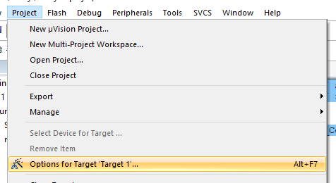
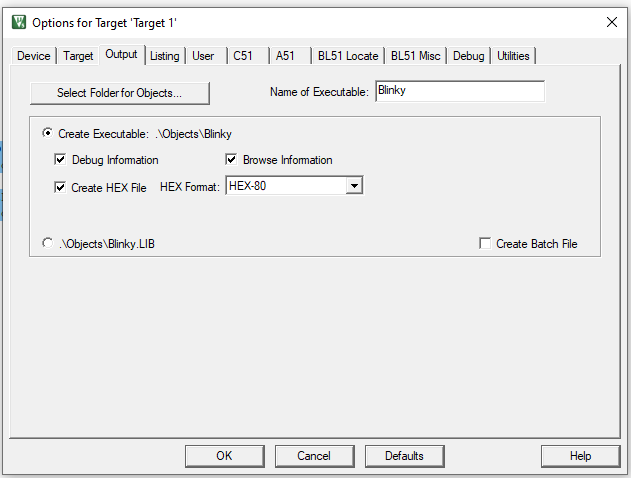
- Go to Project -> Options for Target.. or Alt + F7
- Go to Output tab, check the Create HEX file checkbox and then press Ok to close.
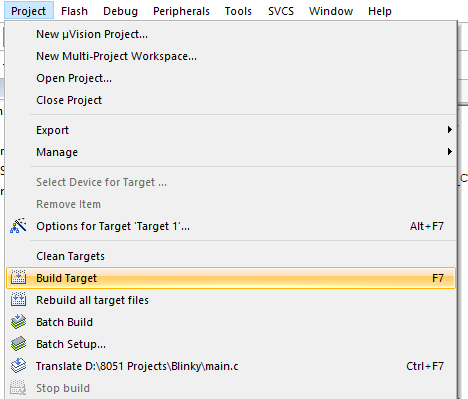
- Build target or Press F7
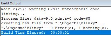
- Look at Build Output for any errors
- If the build is successful, the hex file will be at Project Name > Objects > Project Name.hex
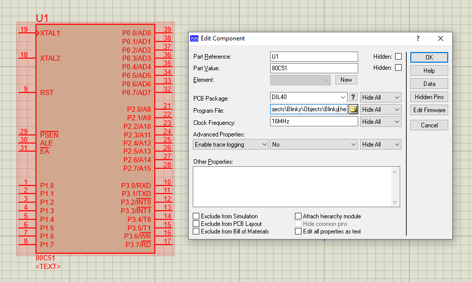
- It's time to simulate the code we just created. For us, we use Labcenter Electronics' Proteus ISIS. Open Proteus ISIS, use the component picker to find 80C51. This is one of the many equivalent models for the AT80C51RD2.
- Right click on 80C51, on Program File field, paste the location of the .hex file
- Press Play. Pin P2.0 should now be flashing
Flashing a LED
The I/O pins for the 8051 microcontrollers are grouped into ports similar to PICs and AVR microcontrollers. Each pin in a port can be set or clear by writing values to the port.
P2 = 0x01;            // Turn ON LED at P2.0
DELAY_ms(500);        // 0.5 second delay

P2 = 0x00;            // Turn OFF LED at P2.0
DELAY_ms(500);        // 0.5 second delay
Here, we write 0x01 to set P2.0 followed by a half-second delay. We then cleared that same pin by writing 0x00.
The DELAY routine is needed in order for us to see the flashing. There's no built-in delay() function unlike in Arduino or XC8 so we had to build one:
// delay subroutine
void DELAY_ms(unsigned int ms_Count)
{
    unsigned int i,j;
    for(i=0;i<ms_Count;i++)
    {
        for(j=0;j<100;j++);
    }
}
The 8051 has an instruction cycle speed of
This means for a 12 MHz oscillator (the default oscillator for 80C51 in Proteus), each instruction is executed in 1 microsecond. In the DELAY routine above, an inner loop counts for a hundred microseconds while an outer loop counts for an interval given by the user in milliseconds. For example, if ms_Count is 500, and a for loop takes about 10 cycles, then the routine will count 500 x 100 x 10 microseconds --- equivalent to half a second.
Another way is to directly set or clear the pin. To do that, we need to declare a variable representing a single pin.
sbit LED = P2^0
The sbit keyword defines a bit within a register (SFR). It may be used like any of these three:
sbit name = sfr-name ^ bit-position;
sbit name = sfr-address ^ bit-position;
sbit name = sbit-address;
Here, our SFR (special function register) is P2 and the bit position is 0.
So to set or clear a pin, we can now use:
LED = 1; 		// Turn ON LED at P2.0
DELAY_ms(500);		// 0.5 second delay

LED = 0; 		// Turn OFF LED at P2.0
DELAY_ms(500);		// 0.5 second delay
To strobe LEDs, we can simply write values to the P2 register in succession.
#include <reg51.h>       // special function register declarations
                        // for the intended 8051 derivative

// delay subroutine
void DELAY_ms(unsigned int ms_Count)
{
    unsigned int i,j;
    for(i=0;i<ms_Count;i++)
    {
        for(j=0;j<100;j++);
    }
}

// main routine
int main()
{
    while(1)
    {
        P1 = 0x01; 		// Turn ON LED at P2.0
        DELAY_ms(500);		// 0.5 second delay

        P1 = 0x02; 		// Turn OFF LED at P2.0
        DELAY_ms(500);		// 0.5 second delay

	P1 = 0x04; 		// Turn ON LED at P2.0
        DELAY_ms(500);		// 0.5 second delay

        P1 = 0x08; 		// Turn OFF LED at P2.0
        DELAY_ms(500);		// 0.5 second delay

	P1 = 0x10; 		// Turn ON LED at P2.0
        DELAY_ms(500);		// 0.5 second delay

        P1 = 0x20; 		// Turn OFF LED at P2.0
        DELAY_ms(500);		// 0.5 second delay

	P1 = 0x40; 		// Turn OFF LED at P2.0
        DELAY_ms(500);		// 0.5 second delay

	P1 = 0x80; 				// Turn OFF LED at P2.0
        DELAY_ms(500);		// 0.5 second dela
    }
    return (0);
}
Of course, we can also use other ports by simply replacing P1 with P0, P2, or P3.
Using a Switch
Unlike other microcontrollers, the 8051 doesn't use data direction registers. Hence, you can make a pin an output or input pin directly. You can attach a switch like this:
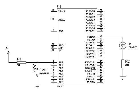
and check its state using a simple if-else statement:
#include <reg51.h> // special function register declarations
                   // for the intended 8051 derivative
sbit LED = P2^0;
sbit SW = P1^0;
// delay subroutine
void DELAY_ms(unsigned int ms_Count) {
  unsigned int i,j;
  for(i=0;i<ms_Count;i++) {
     for(j=0;j<100;j++);
  }
}
// main routine
int main() {
  while(1) {
    if(SW == 0){
      LED = 1;
    }else{
      LED = 0;
    }
  }
  return (0);
}
Here, when the switch at P1.0 is closed, the LED at P2.0 turns on. Otherwise, the LED turns off.
That's it for a short introduction to 8051 microcontroller programming in C. On the next iteration, we'll go deeper into some registers of the 8051 and create interfacing projects using LCDs, sensors, and more!


