
There exists a sensor for almost all physical parameters. Temperature? Pressure? Weight? Gas Concentration? We’ve written a tutorial for them all on this site. This time, we will try to build a device that measures rotational position. The same device can measure rotational speed too. Of course, we’re talking about the rotary encoder.
Types of Rotary Encoder
Absolute Rotary Encoder
There are two general types of rotary encoder. The absolute type, which is more expensive, can track all of its previous positions. Basically, all positions of the knob on a rotary encoder have a value. The way that value is read depends on what sensor the encoder uses: magnetic, optical, or mechanical.
Consider the optical encoder below:

The disk divides into 16 areas with each area having a corresponding binary or gray code value. The way to determine the current position is by passing through a light source on the disk. As shown, each area or position has four windows; a light source and receiver are placed in each of these windows.

For example, when the current position is at 1110, the first up to the third windows, being transparent, will receive light. Consequently, the last window, being opaque, will not receive any light. The light receivers will then give out signals according to their received light, Because each window has a unique combination, the current position of the knob can be known.
Incremental Rotary Encoder
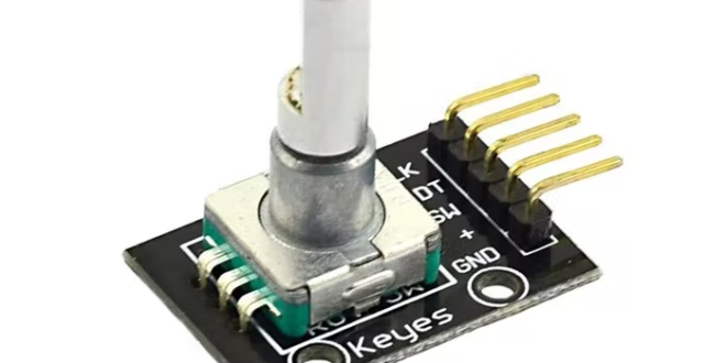
Another type of encoder is the incremental type. Just like the absolute, the incremental encoder is further categorized according to sensor type. The electromechanical type, shown below, is common to electronics hobbyists:
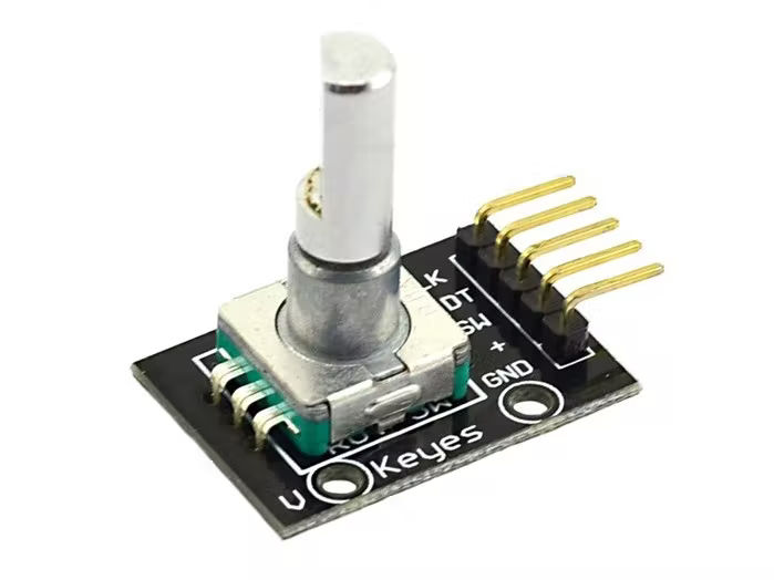
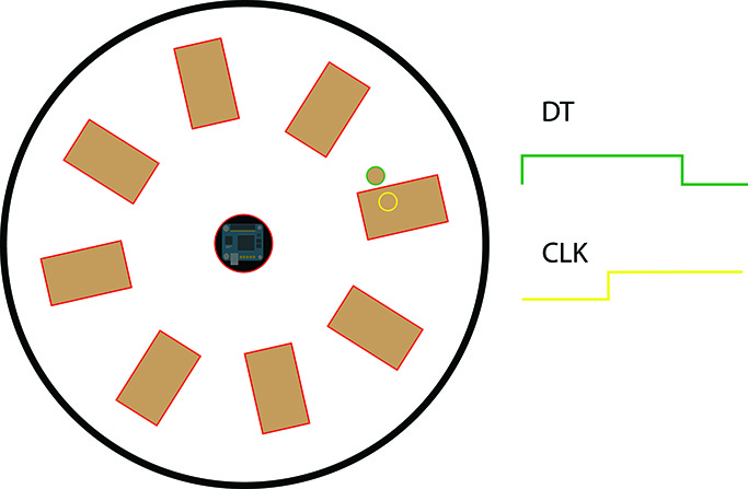
The electromechanical encoder consists of a rotating disk with electrical contacts spaced at 90 degrees. The electrical contacts are wired through the “+” pin while the rest of the space is connected to the “GND” pin. The DT and CLK pin’s position on the disk is shown below.

Note: the SW pin connects to the button which is the center knob.
As you rotate the knob and the disk spins, the DT or CLK pin comes in contact with the electrical contacts.
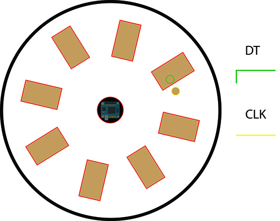
In the figure above, the disk rotates counter-clockwise and the DT pin connects to the electrical contact. A voltage in this pin is equal to the applied voltage in the “+” pin.
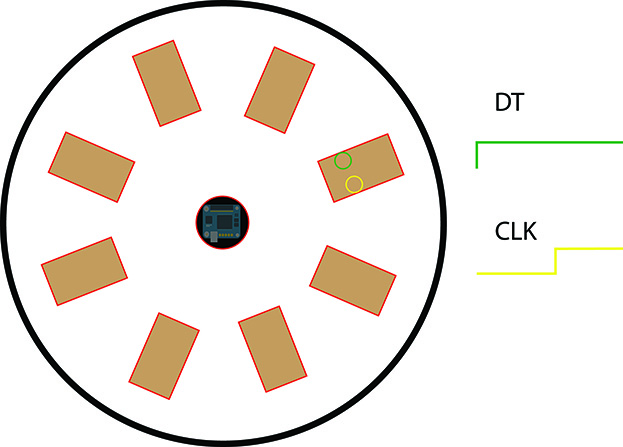
The disk rotates counter-clockwise again and now both DT and CLK pins have a voltage equal to that of the “+” pin.
The DT pin leaves the electrical contact on the next spin and its voltage level goes back to 0 V.

The CLK pin also now leaves the electrical contact, and both pins are like they were in their starting positions.
Direction of Rotation
The rotation of the disk produces pulses in both DT and CLK pins. But, depending on the direction of the rotation, one pin’s pulse always leads the other by 90 degrees (equal to the electrical contact spacing).
In the image below, the disk spins counter-clockwise and DT leads CLK by 90 degrees.

By reading and comparing the pulse from either pin, we can determine the direction of rotation of the encoder. But there’s no way to know the exact position of the knob -- we can only know the direction of rotation relative to the original position or the position prior to applying power to the encoder.
There are two things that can happen from the original position: either the disk rotates counter-clockwise or clockwise. In order to detect the rotation, we must check if one of the pins changed state.
In the image above, it will take two clicks of rotation for DT to change state in the counter-clockwise direction or for CLK to change state in the clockwise direction.
Here, we’ll look at DT. If DT went from high to low and CLK is equal to DT, then the rotation is clockwise. On the other hand, if we rotate counter-clockwise, DT will not change state. But from that, when we rotate counter-clockwise again, DT went from high to low but CLK is now high. This happens regardless of the original position of DT and CLK. This helps us arrive at an algorithm for determining the direction of rotation.
Code for Knowing Rotary Encoder Position
We assign a variable encoder_value that decrements or increments according to the direction of rotation.
int encoder_value;
Then we check the state of the DT and CLK pins (assuming we have already declared them as input pins):
if (DT_pinstate != last_DT_pinstate) { //did DT changed state?

  if (digitalRead(CLK_pin) == DT_pinstate) { // if DT changed state, check CLK

    encoder_value--; // rotation is clockwise, decrement the value

  }else{

    encoder_value++; // rotation is counter-clockwise, increment the value

  }

  last_DT_pinstate = DT_pinstate; //save the last state of DT

}
Then, you can use the encoder_value anywhere: print serially, send to web server, display to LCD, etc.
Here’s a full Arduino code where the encoder value is printed out of the serial port:
int encoder_vaue = 0;
int DT_pin = 6;
int CLK_pin = 7;
int DT_pinstate;
int last_DT_pinstate;

void setup() {
  pinMode (DT_pin, INPUT);
  pinMode (CLK_pin, ,INPUT);

  Serial.begin (9600);

  // Reads the initial state of DT
  last_DT_pinstate = digitalRead(DT_pin);
}

void loop() {
  if (DT_pinstate != last_DT_pinstate) { //did DT changed state?
    if (digitalRead(CLK_pin) == DT_pinstate) { // if DT changed state, check CLK
       encoder_value--; // rotation is clockwise, decrement the value
    }else{
       encoder_value++; // rotation is counter-clockwise, increment the value
    }
  last_DT_pinstate = DT_pinstate; //save the last state of DT
  Serial.print("Position: ");
  Serial.println(encoder_value);
  }

  last_DT_pinstate = DT_pinstate; // Updates the previous state of DT with the current state
}
Using Interrupts
While our code works, there might be instances that DT’s change of state is missed, resulting in a delay in changing encoder_value. Another case is when your code needs to do other important things inside the loop(). Hence, we can further improve our code with the use of interrupts.
Pins D2 and D3 on the Arduino UNO are external interrupt pins. We assign DT and CLK to these pins so that we can detect the change in state without using digitalRead() inside loop().
Then, we create an interrupt handler that triggers every time DT changes state. This is now where we increment encoder_value.
Measuring Speed
You can measure the speed of rotation of the encoder by counting the steps it took for a full rotation, over a period of time. This is much more possible using interrupts than without because we can avoid missing pulses.
Here's a code that displays the speed in rpm, and angular velocity:
// Motor encoder output pulses per 360 degree revolution (measured manually)
#define ENC_COUNT_REV 620

volatile long encoder_value = 0;

// One-second interval for measurements
int interval = 1000;

// Counters for milliseconds during interval
long previousMillis = 0;
long currentMillis = 0;

// Variable for RPM measuerment
float rpm = 0;

// Variable for angular velocity measurement
float angular_velocity = 0;
float angular_velocity_deg = 0;

const float rpm_to_radians = 0.10471975512;
const float rad_to_deg = 57.29578;

int DT_pin = 2;
int CLK_pin = 3;

void setup() {
  pinMode(DT_pin , INPUT_PULLUP);
  pinMode(CLK_pin , INPUT);

  Serial.begin(9600);

  // Every time the pin goes high, this is a pulse
  attachInterrupt(digitalPinToInterrupt(DT_pin), interrupt_on_pulse, RISING);

}

void loop() {

  // Record the time
  currentMillis = millis();

  // If one second has passed, print the number of pulses
  if (currentMillis - previousMillis > interval) {

    previousMillis = currentMillis;

    // Calculate revolutions per minute
    rpm = (float)(encoder_value * 60 / ENC_COUNT_REV);
    angular_velocity = rpm * rpm_to_radians;
    angular_velocity_deg = angular_velocity * rad_to_deg;

    Serial.print(" Pulses: ");
    Serial.println(encoder_value);
    Serial.print(" Speed: ");
    Serial.print(rpm);
    Serial.println(" RPM");
    Serial.print(" Angular Velocity: ");
    Serial.print(angular_velocity_deg);
    Serial.println(" deg per second");
    Serial.println();

    encoder_value = 0;
  }
}

// Increment the number of pulses by 1
void interrupt_on_pulse() {

  // Read the value for the encoder for the right wheel
  int val = digitalRead(CLK_pin);

  if(val == LOW) {
    encoder_value++;
  }
  else {
    encoder_value--;
  }
}
In the code above, we set the number of pulses for one rotation to 620. This is typical for the incremental rotary encoder featured here. If your encoder looks different, try rotating the knob a full rotation and note the encoder value (using the code in this section) seen on serial monitor.
Arduino Rotary Encoder Library
While it is entirely possible to use rotary encoders without a library, you’ll save time and effort if you just use one. Mathertel’s library is enough for basic use, including the use of interrupt for better task management.
Here’s a code snippet from the library that polls the encoder, without interrupts:
// Setup a RotaryEncoder with 2 steps per latch for the 2 signal input pins:
RotaryEncoder encoder(PIN_IN1, PIN_IN2, RotaryEncoder::LatchMode::TWO03);
void setup()
{
  Serial.begin(115200);
  while (! Serial);
  Serial.println("SimplePollRotator example for the RotaryEncoder library.");
} // setup()

// Read the current position of the encoder and print out when changed.
void loop()
{
  static int pos = 0;
  encoder.tick();
  int newPos = encoder.getPosition();
  if (pos != newPos) {
    Serial.print("pos:");
    Serial.print(newPos);
    Serial.print(" dir:");
    Serial.println((int)(encoder.getDirection()));
    pos = newPos;
  } // if
} // loop ()</pre>
And here’s one with interrupt:
void setup()
{
  Serial.begin(115200);
  while (!Serial);
  Serial.println("InterruptRotator example for the RotaryEncoder library.");
  // use TWO03 mode when PIN_IN1, PIN_IN2 signals are both LOW or HIGH in latch position.
  encoder = new RotaryEncoder(PIN_IN1, PIN_IN2, RotaryEncoder::LatchMode::TWO03);
  // register interrupt routine
  attachInterrupt(digitalPinToInterrupt(PIN_IN1), checkPosition, CHANGE);
  attachInterrupt(digitalPinToInterrupt(PIN_IN2), checkPosition, CHANGE);
} // setup()

// Read the current position of the encoder and print out when changed.
void loop()
{
  static int pos = 0;
  encoder->tick(); // just call tick() to check the state.
  int newPos = encoder->getPosition();
  if (pos != newPos) {
    Serial.print("pos:");
    Serial.print(newPos);
    Serial.print(" dir:");
    Serial.println((int)(encoder->getDirection()));
    pos = newPos;
  } // if
} // loop ()
Note that the library supports ESP8266 as well.
Did this article help you understand rotary encoders for Arduino? If it did, kindly drop a comment below!


 Sensor")

