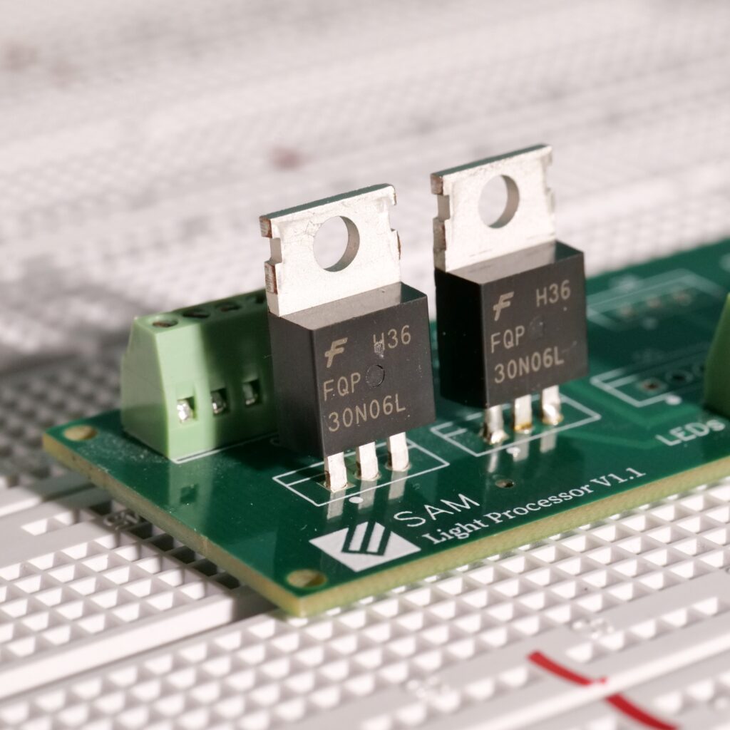
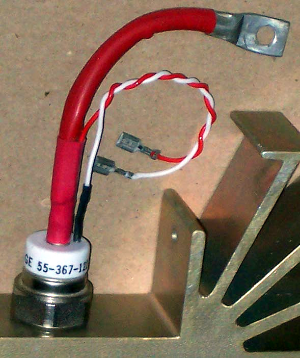
MOS tubes are a requirement for developing a power supply or drive circuit. MOS tubes are available in a wide range of colors, patterns, and sizes. Use the power supply's or the drive's switching feature, of course.
The working principle of a MOS tube is essentially the same whether it is N-type or P-type. In a MOS transistor, the current flowing through the drain terminal of the output terminal is controlled by the voltage applied to the gate of the input terminal.

A MOS tube is a voltage-controlled device. The device's properties are managed by the voltage applied to the gate, which prevents the charge storage effect brought on by base current during transistor switching. As a result, the MOS tube's switching speed in switching applications should be higher than the triode's.
MOS tubes' PDF properties are frequently examined. The RDS(ON) parameter is used by MOS tube makers to specify the on-resistance. The most crucial device feature for switching applications is RDS(ON).
Despite being a relatively static feature for a good gate drive, RDS(ON) is specified in the datasheet in relation to the gate (or drive) voltage VGS and the current flowing through the switch. It is simple to heat an open MOS tube normally. Additionally, RDS(ON) will rise as junction temperature rises gradually.
The MOS tube data sheet defines the thermal impedance parameter as the ability of the semiconductor junction of the MOS tube package to dissipate heat. The simplest definition of RJC is the heat resistance between the junction and the casing.
The MOS tube current heat is minimal for the following reasons:
1) Make the MOS tube operate in a linear working condition rather than a switching state, which is one of the causes of the MOS tube heating.
The G-level voltage of the P-MOS switch is the opposite of the G-level voltage of the N-MOS switch, which is a few V higher than the power supply to be fully turned on. It is not fully opened, generating an excessive voltage drop that consumes energy; the equivalent DC impedance is rather high; the voltage drop causes an increase in U*I, which results in an increase in heat production; and the voltage drop causes an increase in U*I. The worst error in circuit design is this.
2) The frequency is too high: The major cause is that occasionally excessive volume-driven frequency increases and MOS tube loss results in higher heat generation.
3) Poor heat dissipation design: The current is excessively high, and the MOS tube needs good heat dissipation to operate at its rated current value. Since a lot of heat may be produced if the ID is lower than the maximum current, a second heat sink may be required.
4)The wrong MOS tube was chosen because the internal resistance of the MOS tube was not fully taken into account and the power evaluation was erroneous, increasing the switch impedance.
How to stop small current mos tubes from being severely heated:
(1) Design the MOS tube's heat dissipation well, and include appropriate auxiliary heat sinks.
(2) The radiator is painted.
MOSFETs inhibit reverse power supply for what reason?
The circuit will be harmed if the power is reversed, which is an inevitable circumstance. We must include a protective circuit in the circuit to ensure that it won't be destroyed even if the power is reversed.
The majority of the time, this can be fixed by attaching a diode to the positive terminal of the power source, but the circuit will suffer high losses due to the voltage drop across the diode, especially if it is powered by a battery. V, significantly reduced battery life.
The low voltage loss while utilizing MOS tubes for anti-reverse connections is a benefit. The current MOS tube can have an internal resistance of several milliohms if its internal resistance is 6.5 milliohms, the current flowing through it is 1A (which is already a significant current), and the voltage drop is just 6.5 millivolts.
People progressively begin to employ MOS tubes to prevent reverse power supply connections as they become more affordable.


