Sponsored content. Written by Gabriel Stik, founder of SpeakCAD, the browser CAD tool used in this tutorial.
AI mesh generators can make an ESP32 case that looks right in a few seconds. The trouble starts when you put the board in: the USB opening is a few millimetres off, the board sits on nothing, and the lid hits the module. A mesh generator draws a shape that resembles a case. It doesn't know where your board's connector is.
This tutorial works the other way round. You start from the board's published dimensions, decide how the board sits and where the wires leave, add clearances that suit FDM printing, and only then build the case. The example is Espressif's ESP32-DevKitC V4, but the method works for any board.
Fit-test status: This case was designed and checked in CAD. It has not been printed or fitted on a real board yet, so print the two test pieces first.
What you need
- An ESP32-DevKitC V4, or the board you want to enclose
- Female jumper wires, if you'll connect anything to the header pins
- Digital calipers
- A 3D printer and PLA
- A CAD tool where you type dimensions. This example uses SpeakCAD, which runs in the browser; OpenSCAD, FreeCAD and Fusion follow the same steps.
Step 1: Get the board’s numbers
Espressif publishes a dimension drawing for the DevKitC V4 (PDF and DXF, linked from the board's user guide). These are the numbers that matter for an enclosure:
| Feature | Value |
|---|---|
| PCB | 48.26 x 27.94 mm, 1.6 mm thick |
| WROOM module | 25.5 x 18 mm, centred across the width |
| Module overhang | the antenna end sticks out 6.04 mm past one short end, so the board is 54.3 mm long overall |
| Header rows | 2 x 19 pins, 2.54 mm pitch, 1.27 mm in from each long edge |
| Micro-USB | centred on the short end opposite the antenna, about 1 mm past the PCB edge |
| EN and BOOT buttons | either side of the USB connector, 8 mm from its centre line, about 4 mm in from that end |
| Mounting holes | none |
The drawing is flat, so it gives no heights. Measure these on your own board:
- the module's top above the PCB: about 3.1 mm on a WROOM-32E;
- the USB connector's top above the PCB: about 3 mm;
- how far the header pins reach below the PCB: about 8.5 mm with standard headers, a 2.5 mm plastic spacer plus 6 mm of pin;
- the length of your female jumper housings: 14 mm on standard Dupont jumpers.
Then check the outline with calipers. Boards sold as "ESP32 DevKit" vary: the 30-pin DOIT DevKit V1, for example, has a different width and pin spacing. A drawing is only right for the board it describes.
Step 2: Decide how the board sits and where the wires go
The DevKitC has no mounting holes, so screw posts are out. Its pins also hang below the board along both long edges, which rules out ledges at the edges. With jumpers pushed on, the housings reach 16.5 mm below the PCB, and each wire needs room to bend.
So the board sits on two rails under the PCB, inboard of the pin rows:
- Rails: 2 mm wide, centred 6 mm in from each long edge of the PCB. They're 22.5 mm tall: 2.5 mm of header spacer, 14 mm of jumper housing and 6 mm for the wire to bend. They run wall to wall, which keeps them stiff.
- Wire slots: the housings hang between each rail and its wall, and the wires bend along the floor. A 20 x 6 mm slot at floor level in each long wall lets them out, one slot per pin row, since the rails stop wires from crossing over.
- Hold-down: two 4 mm posts under the lid rest on the module's metal shield, clear of the antenna. They keep the board on the rails, with no screws or glue.
If you won't attach any wires, you can cut the rails to 9 mm (the pins plus 0.5 mm), and the case gets 13.5 mm lower.
Step 3: Add clearances that suit FDM printing
A printed hole always comes out a little smaller than designed, because extruded plastic spreads and the first layers squash outwards. That's why the cavity is never the board's exact size:
- Board outline: 0.3 mm all round. The cavity is 54.9 x 28.54 mm for a 54.3 x 27.94 mm board.
- USB window: size it for the plug, not the socket. The socket is about 8 mm wide, but the plug's moulded body is wider and taller. A 12 x 8 mm window, centred 1.5 mm above the PCB's top, lets a normal cable in. Because the walls rise 4 mm above the module, it stays a closed hole with 1.6 mm of wall over it. On a lower case it would become a notch, and the lid would need a matching one.
- Lid lip and snap: 0.3 mm. The lid has a 2 mm deep, 1.2 mm thick lip that drops 0.3 mm inside the walls. On each long side of the lip, a 30 mm bump of 0.55 mm radius reaches 0.25 mm past the wall's face. That 0.25 mm is the click. Once the lid is closed, the bump rests in a 0.5 mm groove 1 mm below the top of the wall.
- Headroom: 4 mm above the module. The posts are 4 mm long, so they touch the module's top with no gap. Printed parts vary by a tenth of a millimetre or two; if the board still rocks, put a small piece of foam tape on each post.
If your printer runs tight or loose, change these numbers rather than sanding the print.
Every number in one place
| Part | Value |
|---|---|
| Outside | 58.9 x 32.5 mm; base 33.2 mm tall, 35.2 mm with the lid on; 3 mm corner radius |
| Walls and floor | 2 mm |
| Cavity | 54.9 x 28.54 mm (0.3 mm around the board) |
| Rails | 2 mm wide, 22.5 mm tall, centred 6 mm in from the PCB's long edges, wall to wall |
| PCB | sits 24.5 mm above the bottom of the base |
| USB window | 12 x 8 mm closed hole in the end wall, on the centre line, centre 1.5 mm above the PCB's top (27.6 mm above the bottom) |
| Wire slots | 20 x 6 mm at floor level, centred in each long wall |
| Lid | 2 mm plate; lip 2 mm deep, 1.2 mm thick, 0.3 mm from the walls |
| Snap | 30 mm bumps of 0.55 mm radius on the lip's long sides; 0.5 mm grooves, 1 mm below the top of the wall |
| Hold-down posts | 4 mm across, 4 mm long, on the centre line, 12 and 21 mm from the module's antenna end |
| Button holes | 3.5 mm, 8 mm either side of the centre line, 4 mm in from the PCB's USB end |
| Headroom | 4 mm from the module's top to the lid |
Step 4: Build the case
With the numbers written down, the case is quick to build. Either route below gives you the same case.
Route 1: describe it. In SpeakCAD, start a new model and paste this prompt:
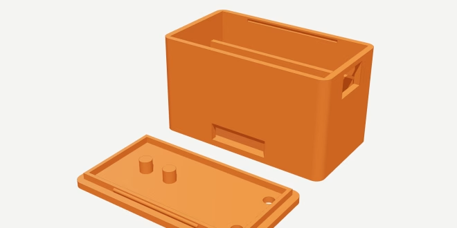
Two-piece enclosure for an Espressif ESP32-DevKitC V4: a base and a snap-on lid, printed side by side with no supports (base upright, lid upside down).

The board: PCB 48.26 x 27.94 x 1.6 mm, no mounting holes. The WROOM module is 25.5 x 18 mm and 3.1 mm tall, centred across the width, and overhangs one short end of the PCB by 6.04 mm. The micro-USB socket is centred on the other short end and sticks out 1 mm past the PCB. The EN and BOOT buttons are 8 mm either side of the centre line, 4 mm in from the USB end. The header pins hang 8.5 mm below the PCB, in two rows of 19 at 2.54 mm pitch, 1.27 mm in from each long edge.

Base: 2 mm walls and a 2 mm floor, 3 mm outer corner radius, and 0.3 mm clearance all round the board's outline (the PCB plus the module's overhang). The board sits on two rails, 2 mm wide and 22.5 mm tall, centred 6 mm in from each long edge of the PCB and running the full inside length, so female jumper wires can push onto the pins and bend under the board. A 12 x 8 mm USB window through the end wall, centred on the socket 1.5 mm above the PCB top, as a closed hole. A 20 x 6 mm wire slot at floor level in the middle of each long wall. The walls end 4 mm above the top of the module.

Lid: a 2 mm plate with a 2 mm deep, 1.2 mm thick lip that fits inside the walls with 0.3 mm clearance. On each long side of the lip, a 30 mm long snap bump of 0.55 mm radius that clicks into a matching 0.5 mm radius groove in the wall. Two 4 mm posts under the lid, on the centre line, 12 mm and 21 mm from the module's antenna end, reaching down to the module's top so they hold the board on the rails. Two 3.5 mm holes above EN and BOOT.

Add two fit checks. Board pocket: a ring of the base from 2 mm below the header pin tips to 2 mm above the PCB top, so the board stands on the rails with its pins clear of the table. Lid snap: the top 4 mm of the walls, with the groove, and the whole lid.
SpeakCAD's AI writes an OpenSCAD program from it in a few minutes, and every size appears as a named dimension you can retype. AI requests use credits; retyping a dimension doesn't call the AI. The AI can word its program differently from one run to the next, so compare its dimensions with the table above before you print.
Route 2: start from the file. Download esp32-devkitc-case.scad from the files at the end and open it in OpenSCAD, which is free. Every number above is in its Customizer panel with a label, so you change the case there, not in the code. You can also attach the file to a SpeakCAD chat and ask for the same model.
Whichever route you take, check four things before you print:
- the USB window's centre is on the board's centre line;
- the button holes sit above EN and BOOT, measured from the USB end;
- each rail is at least 2 mm from the jumper housings beside it;
- the posts land on the module's metal shield, not on the antenna end.
Step 5: Print two test pieces first
The base takes about 45 minutes on a Bambu Lab A1 at 0.2 mm layers. Two smaller pieces tell you whether it will fit before you spend that, and one of them is the finished lid.
The board ring (fit-test-board.stl, about 22 minutes, 8 g) is the band of the base around the PCB, from 14 mm to 28.1 mm up. It has no floor and needs none. Its rail sections are 10.5 mm tall and the pins hang 8.5 mm, so when you stand the ring on the table and drop the board onto the rails, the pin tips stay 2 mm clear of the table. Test it without jumper wires:
- the board should drop in without force, move about 0.3 mm each way and sit level on both rails;
- the USB socket should line up with the bottom of the window, which is open at the top in the ring, and a cable should plug straight in.
If the board is tight, add 0.1 to 0.2 mm to the board clearance and print the ring again.
The lid test (fit-test-lid.stl, about 19 minutes, 6 g) is the top 4 mm of the walls, with the snap grooves, plus the whole lid. Press the lid onto the ring: it should click in with light force and not rattle. The thin ring flexes a little more than the full base, so expect the real lid to snap slightly firmer. If it doesn't click, add 0.05 mm to the bump radius; if it's hard to close, take 0.05 mm off. Once it clicks, keep this lid and print only the base.
To make test pieces for your own design, use a slicer's Cut tool (PrusaSlicer, OrcaSlicer and Bambu Studio all have one): cut the base 2 mm below the pin tips and 2 mm above the PCB for the ring, and 4 mm below the rim for the snap. In SpeakCAD, the Fit check button makes them from the model. Downloading a test piece costs no credits, and once you've tried it, you tell SpeakCAD whether it was too tight, right or too loose, so it can adjust the clearances for your printer.
Step 6: Print the case
Suggested settings for PLA:
- 0.2 mm layers, 3 walls, 15% infill;
- the base upright, the lid upside down with its top face on the bed;
- no supports: the wire slots and the USB window are short bridges, and the posts point up.
On a Bambu Lab A1 the slicer estimates 45 minutes and 21.5 g for the base, or 53 minutes and 26.3 g with the lid.
Step 7: Assemble
- Push the female jumpers onto the pins you need, from below.
- Pass their free ends out through the slot on the same side.
- Tilt the board with its antenna end up, lower the USB end until the socket lines up with the window, and slide it in so the socket enters the window.
- Lower the antenna end onto the rails.
- Press the lid on until both sides click. The posts now rest on the module.
You can reach EN and BOOT through the lid holes with a toothpick or a straightened paperclip.
Files
esp32-devkitc-case.stl: the base and lid, laid out to print [Download link to be added before publication]fit-test-board.stlandfit-test-lid.stl: the two test pieces [Download link to be added before publication]esp32-devkitc-case.scad: the editable design; it opens in OpenSCAD [Download link to be added before publication]- Espressif's ESP32-DevKitC V4 dimension drawing
I designed the case from Espressif's drawing and checked it in CAD against a model of the board, its header pins and standard jumper housings. Printers differ, so print the two test pieces before the full case.
The method is the useful part: get the board's numbers, decide how it sits and where the wires go, add printing clearances, test the fit with small pieces, then print the whole thing. It works the same for an ESP32-C3, an Arduino Nano or a Raspberry Pi Pico.
For board-specific pin details, see the ESP32-WROOM-32 pinout and our ESP32-C3 Super Mini guide.