
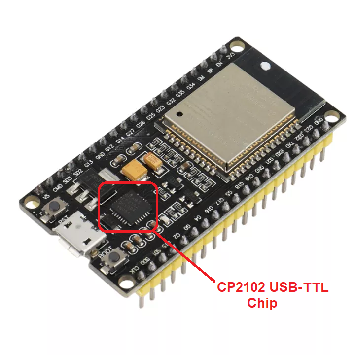
The serial port is the most usual comm channel between a microcontroller and a computer. However, the different voltage levels and loss of the RS-232 port in modern computers led to the use of USB-TLL converter chips like CH340, CP2102, etc.
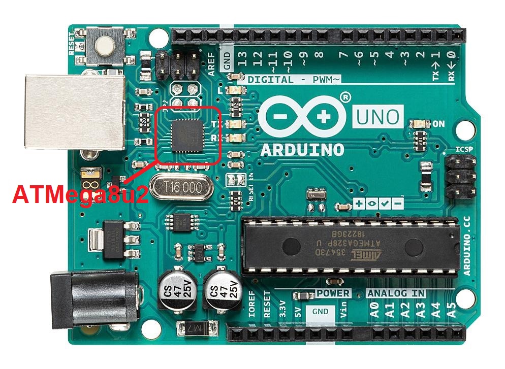
This is what happens in the NodeMCU ESP8266 and ESP32. Another example, the Arduino UNO, uses an extra microcontroller just for its USB interface.
Adding another chip would entail costs in both part counts in PCB space. Thankfully, the STM32F4 microcontroller provides a neat solution.
What is CDC?
Communications Device Class (CDC) is one of many device classes specified by the USB protocol. Its primary use is for “computer networking devices akin to a network card, providing an interface for transmitting Ethernet or ATM frames onto some physical media. It is also used for modems, ISDN, fax machines, and telephony applications for performing regular voice calls.”
With CDC, a USB device acts like a normal serial port device. You can then send and receive messages serially from/to the computer. Since it’s not a “real” COM port, CDC devices are also called Virtual COM Ports.
Setting Up STM32 USB CDC
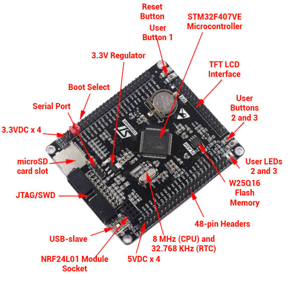
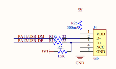
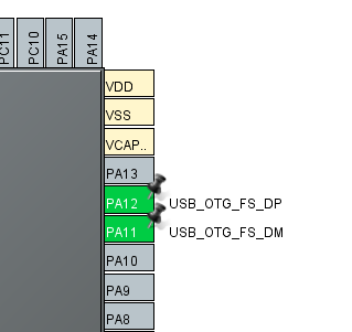
For this tutorial, I will be using the STM32F4 Black Board. This board doesn’t come with any USB-TLL converter or ST-Link, unlike the STM32 Discovery line. It does come with a miniUSB port, whose D-, and D+ pins are wired to pins PA11 and PA12.
The application will control the onboard LEDs via sending characters thru CDC. For reference, the onboard LEDs are at PA6 and PA7.
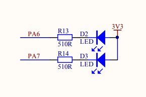
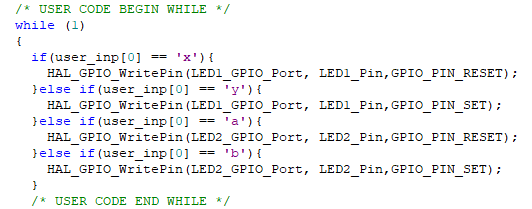
When an “x” is received, D2 lights up. When a “y” is received, D2 turns off. Alternatively, when an “a” is received, D3 lights up and when a “b” is received, D3 turns off.
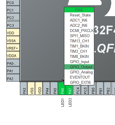
It’s time to run STM32CubeMX! First up, we set the GPIO pins for the LEDs.
Make both PA6 and PA7 output pins:
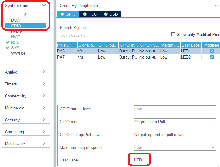
To rename them, just go to System Core > GPIO and assign user labels:
Next, we make use of the 8 MHz crystal on the board. Set the PHO and PH1 pins as RCC pins.
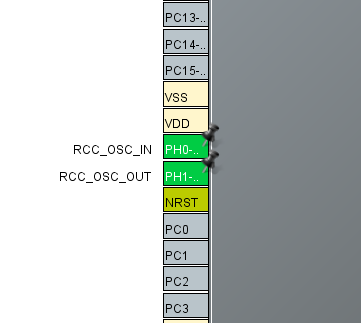
Go to System Core > RCC and select Crystal/Ceramic Resonator as High Speed Clock source.
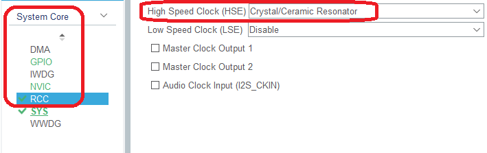
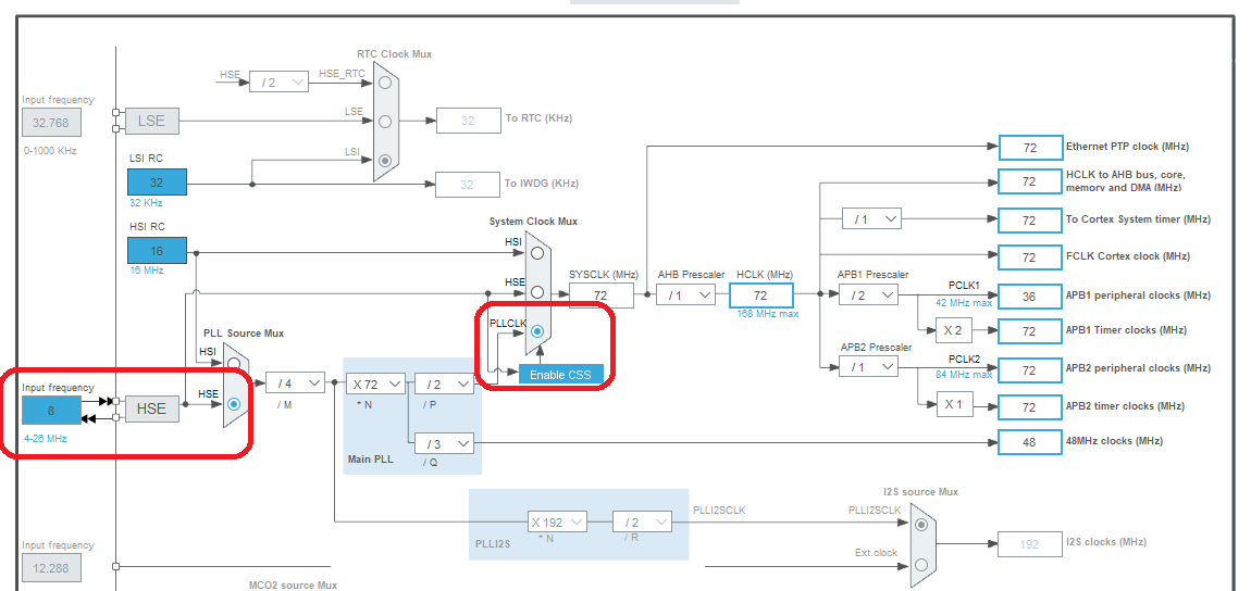
At this point, you can go to the Clock Configuration tab and change the input frequency to 8 MHz, HSE.
Of course, we still need to enable USB. Change pins PA11 and PA12 to their USB_OTG alternate functions.
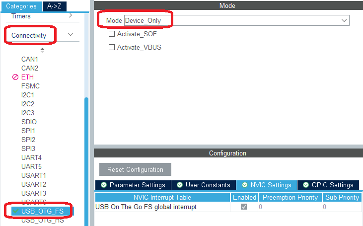
Then go to Connectivity > USB_OTG_FS and select Device_Only mode.
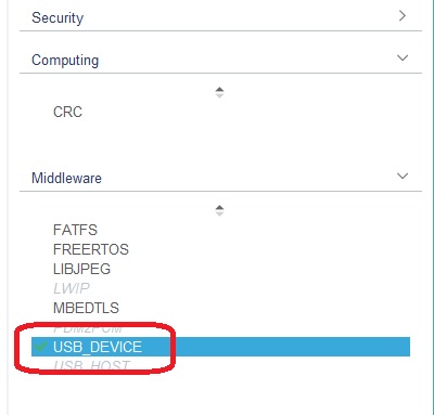
Next, go to Middleware > USB_DEVICE:
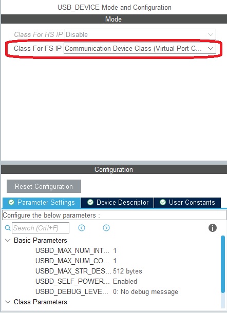
On the dropdown on the right window, select Communication Device Class:
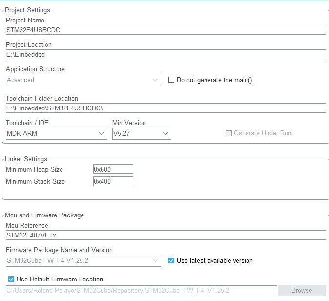
Finally, go over to Project Configuration, name your project, select a location to save it, and specify the toolchain (MDK-ARM if you’re using Keil). You may also need to change the heap size to 0x800 if you’re encountering problems whenever you’re plugging in the STM32F4 board on your computer.
Click “Generate Code” and open Keil.
Receiving Data from PC to STM32
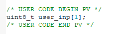
In main.c, declare a variable that will serve as our buffer for user input. I placed mine between the Private Variables section:
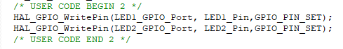
Just before the while(1) loop in int main, turn off the LEDs:
Inside the while(1) loop, we insert the part where we check the serial input and control the LEDs accordingly:
We’re not done yet! Open the file usbd_cdc_if.c. This is where all the implementing functions for CDC are found.
Declare the same variable we used as buffer in main.c:
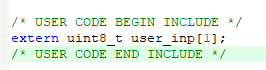
The keyword extern means it’s the same variable on main.c. This gives user_inp[] a global scope between the two files.
Locate the function CDC_Receive_FS() and add the following lines.
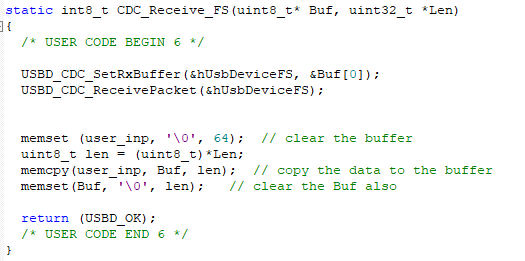
This function is a callback function that auto triggers whenever there is a received message thru CDC. That message is saved to the memory pointed by Buf, and its length is given by Len. All we have to do is copy that message to user_inp using memcpy. Before that, we must make sure that user_inp does not retain its previous value. This is what the first memset() does. The second memset is for clearing the Buf variable once we have transferred its contents to user_inp.
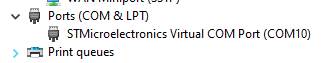
That’s about it for the code. Build and flash it to the board. As soon as you connect the board to the computer via USB, it will appear as a COM port in Device Manager:
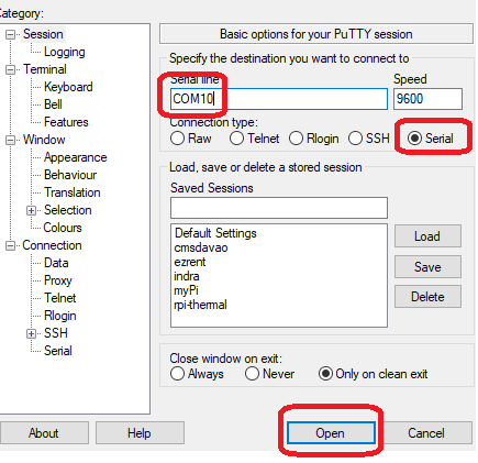
Using a terminal application like Putty, we can now send messages to the STM32F4 Black Board from the computer.
Here's the output of this application:
Sending Data From STM32 to PC
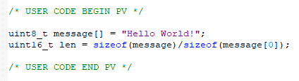
If there’s a function for receiving data, there’s also one for transmitting:
This function accepts two parameters: the data to be sent, and its length.
You can set those parameters like this:
Also, you need to define the prototype function with extern command:

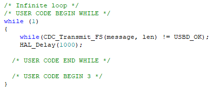
Finally, you can send messages. Here’s an example that sends a message every second:
I hope you found this tutorial on STM32 CDC USB useful. Happy coding!

